Information injection-pump assembly
ZEXEL
101696-9800
1016969800
NISSAN-DIESEL
16713Z6762
16713z6762

Rating:
Cross reference number
ZEXEL
101696-9800
1016969800
NISSAN-DIESEL
16713Z6762
16713z6762
Zexel num
Bosch num
Firm num
Name
Calibration Data:
Adjustment conditions
Test oil
1404 Test oil ISO4113 or {SAEJ967d}
1404 Test oil ISO4113 or {SAEJ967d}
Test oil temperature
degC
40
40
45
Nozzle and nozzle holder
105780-8260
Bosch type code
9 430 610 133
Nozzle
105780-0120
Bosch type code
1 688 901 990
Nozzle holder
105780-2190
Opening pressure
MPa
18
Opening pressure
kgf/cm2
184
Injection pipe
Outer diameter - inner diameter - length (mm) mm 6-2-600
Outer diameter - inner diameter - length (mm) mm 6-2-600
Overflow valve
131425-0420
Overflow valve opening pressure
kPa
157
123
191
Overflow valve opening pressure
kgf/cm2
1.6
1.25
1.95
Tester oil delivery pressure
kPa
255
255
255
Tester oil delivery pressure
kgf/cm2
2.6
2.6
2.6
Direction of rotation (viewed from drive side)
Right R
Right R
Injection timing adjustment
Direction of rotation (viewed from drive side)
Right R
Right R
Injection order
1-4-2-6-
3-5
Pre-stroke
mm
3.1
3.05
3.15
Beginning of injection position
Drive side NO.1
Drive side NO.1
Difference between angles 1
Cal 1-4 deg. 60 59.5 60.5
Cal 1-4 deg. 60 59.5 60.5
Difference between angles 2
Cyl.1-2 deg. 120 119.5 120.5
Cyl.1-2 deg. 120 119.5 120.5
Difference between angles 3
Cal 1-6 deg. 180 179.5 180.5
Cal 1-6 deg. 180 179.5 180.5
Difference between angles 4
Cal 1-3 deg. 240 239.5 240.5
Cal 1-3 deg. 240 239.5 240.5
Difference between angles 5
Cal 1-5 deg. 300 299.5 300.5
Cal 1-5 deg. 300 299.5 300.5
Injection quantity adjustment
Adjusting point
-
Rack position
13.2
Pump speed
r/min
700
700
700
Average injection quantity
mm3/st.
108
106.4
109.6
Max. variation between cylinders
%
0
-3.5
3.5
Basic
*
Fixing the rack
*
Standard for adjustment of the maximum variation between cylinders
*
Injection quantity adjustment_02
Adjusting point
Z
Rack position
9.2+-0.5
Pump speed
r/min
400
400
400
Average injection quantity
mm3/st.
20
18.2
21.8
Max. variation between cylinders
%
0
-10
10
Fixing the rack
*
Standard for adjustment of the maximum variation between cylinders
*
Injection quantity adjustment_03
Adjusting point
A
Rack position
R1(13.2)
Pump speed
r/min
700
700
700
Average injection quantity
mm3/st.
108
107
109
Basic
*
Fixing the lever
*
Boost pressure
kPa
29.3
29.3
Boost pressure
mmHg
220
220
Injection quantity adjustment_04
Adjusting point
B
Rack position
R1+1.95
Pump speed
r/min
1400
1400
1400
Average injection quantity
mm3/st.
116
112
120
Fixing the lever
*
Boost pressure
kPa
29.3
29.3
Boost pressure
mmHg
220
220
Injection quantity adjustment_05
Adjusting point
I
Rack position
-
Pump speed
r/min
150
150
150
Average injection quantity
mm3/st.
140
140
150
Fixing the lever
*
Boost pressure
kPa
0
0
0
Boost pressure
mmHg
0
0
0
Rack limit
*
Boost compensator adjustment
Pump speed
r/min
400
400
400
Rack position
R2-1.4
Boost pressure
kPa
4
2.7
5.3
Boost pressure
mmHg
30
20
40
Boost compensator adjustment_02
Pump speed
r/min
400
400
400
Rack position
R2(R1-0.
4)
Boost pressure
kPa
16
16
16
Boost pressure
mmHg
120
120
120
Timer adjustment
Pump speed
r/min
-
Advance angle
deg.
1
0.5
1.5
Remarks
Measure speed (beginning of operation).
Measure speed (beginning of operation).
Timer adjustment_02
Pump speed
r/min
-
Advance angle
deg.
0
0
0
Remarks
Measure the actual speed.
Measure the actual speed.
Timer adjustment_03
Pump speed
r/min
-
Advance angle
deg.
0
0
0
Remarks
Measure the actual speed.
Measure the actual speed.
Timer adjustment_04
Pump speed
r/min
-
Advance angle
deg.
4.5
4
5
Remarks
Measure the actual speed, stop
Measure the actual speed, stop
Test data Ex:
Governor adjustment
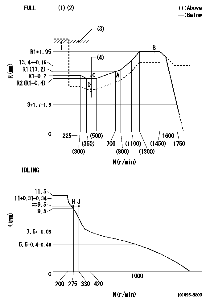
N:Pump speed
R:Rack position (mm)
(1)Torque cam stamping: T1
(2)Tolerance for racks not indicated: +-0.05mm.
(3)RACK LIMIT
(4)Boost compensator stroke: BCL
----------
T1=M62 BCL=1.4+-0.1mm
----------
----------
T1=M62 BCL=1.4+-0.1mm
----------
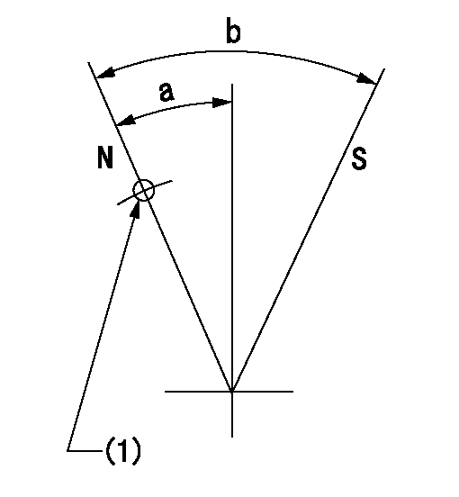
Speed control lever angle

F:Full speed
I:Idle
(1)Use the hole at R = aa
(2)Stopper bolt set position 'H'
----------
aa=39mm
----------
a=20deg+-5deg b=40deg+-3deg
----------
aa=39mm
----------
a=20deg+-5deg b=40deg+-3deg
Stop lever angle
N:Pump normal
S:Stop the pump.
(1)Use the pin at R = aa
----------
aa=42mm
----------
a=25deg+-5deg b=40deg+-5deg
----------
aa=42mm
----------
a=25deg+-5deg b=40deg+-5deg
0000001501 RACK SENSOR
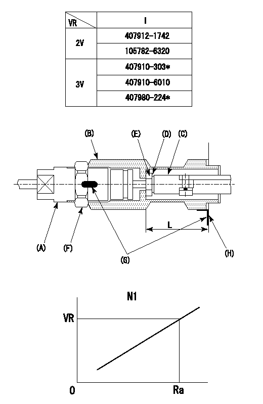
(VR) measurement voltage
(I) Part number of the control unit
(G) Apply red paint.
(H): End surface of the pump
1. Rack limit adjustment
(1)Fix the rack at the rack limit position Ra.
(2)Install the shim (D) to the rod (C) and tighten nut (E).
(3)Select a shim (D) so that the distance between the end surface of the pump and the nut (E) is L.
(4)Release the rack fixing and mount the joint (B) and fix.
(5)At this time, confirm that the shim (D) does not interfere with the joint (B).
2. Rack sensor adjustment (-0420)
(1)Screw in the bobbin (A) until it contacts the joint (B).
(2)Fix the speed control lever at the full side.
(3)Set the speed to N1 r/min.
(4)Adjust the depth that the bobbin (A) is screwed in so that the control unit's rack sensor output voltage is VR+-0.01 (V), then tighten the nut (F).
(5)Adjust the bobbin (A) so that the rack sensor's output voltage is VR.
(6)Apply G at two places.
Connecting part between the joint (B) and the nut (F)
Connecting part between the joint (B) and the end surface of the pump (H)
----------
L=33-0.2mm N1=700r/min Ra=R1(13.2)mm
----------
----------
L=33-0.2mm N1=700r/min Ra=R1(13.2)mm
----------
0000001601 LEVER
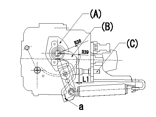
(a) Speed lever
(B) Accelerator lever
(C) Accelerator lever stopper bolt
1. Accelerator lever setting method
With the speed lever in the idling position, back off the accelerator lever stopper bolt L1 from where it contacts point a. (Back off 1+0.5 turns and set.)
----------
L1=1+0.5mm
----------
----------
L1=1+0.5mm
----------
Timing setting

(1)Pump vertical direction
(2)Position of timer's threaded hole at No 1 cylinder's beginning of injection
(3)-
(4)-
----------
----------
a=(60deg)
----------
----------
a=(60deg)
Information:
Illustration 1 g00564355
7W-2743 Electronic Speed Switch (ESS)
(1) Push button for Overspeed Verification
(2) Reset button
(3) Overspeed indicator lamp
(4) Seal screw plug for adjusting the engine overspeed
(5) Seal screw plug for adjusting the crank terminate speed
(6) Seal screw plug for adjusting the oil step pressure speed setting The overspeed calibration can increase the overspeed setting or the overspeed calibration can decrease the overspeed setting in order to shut down the engine when the overspeed verification button is pressed. The overspeed setting is correctly made when the engine is running at 75% of the overspeed setting. The engine then shuts down when the overspeed verification button is pressed.Use the following procedure in order to adjust the overspeed setting.
Remove the lockwire and the seal from seal screw plug (4). Remove seal screw plug (4) from the access hole for the overspeed adjustment screw.
Use a small screwdriver to lightly turn the overspeed adjustment screw in the direction of the "MAX" arrow or the clockwise direction. Turn the screw 20 times. The overspeed adjustment screw will vary the setting of a potentiometer that is inside of the ESS. The overspeed adjustment screw will not cause damage to the potentiometer. Also, the screw can not be removed if the screw is turned in the wrong direction.
Run the engine at 75% of the desired overspeed setting rpm. Refer to the Speed Specification Chart.
While the engine is running at 75% of the overspeed setting rpm, press "VERIFY" button (1). While the button is depressed, slowly turn the overspeed adjustment screw in the opposite direction of the "MAX" arrow or the counterclockwise direction until overspeed indicator lamp (3) is lighted. The engine will shut down if the ESS is connected to the fuel shutoff solenoid (FSOS) and the air shutoff solenoid, if equipped.
In order to reset the ESS, press "RESET" button (2). The air shutoff valve must be reset by hand, if equipped.
Slowly turn the overspeed adjustment screw in the clockwise direction for one turn. Repeat Steps 3, 4, and 5. More adjustment may be necessary in order to gain the correct setting. Turn the overspeed adjustment screw in the clockwise direction in order to increase the overspeed setting. Turn the overspeed adjustment screw in the counterclockwise direction in order to decrease the overspeed setting.
When the overspeed setting is correct, install seal screw plug (4) in the access hole for the overspeed adjustment screw. Tighten the screw to a torque of 0.20 0.03 N m (1.8 .3 lb in). Install the lockwire and the seal if the calibration of the crank termination speed and the oil step speed calibration are also complete.