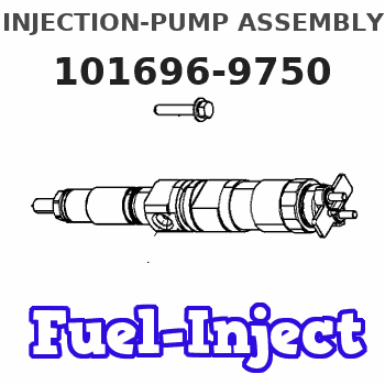
Information injection-pump assembly
ZEXEL
101696-9750
1016969750
NISSAN-DIESEL
16713Z6712
16713z6712

Rating:
Service parts 101696-9750 INJECTION-PUMP ASSEMBLY:
1.
_
7.
COUPLING PLATE
8.
_
9.
_
11.
Nozzle and Holder
16600-Z5607
12.
Open Pre:MPa(Kqf/cm2)
19.6{200}
15.
NOZZLE SET
Cross reference number
ZEXEL
101696-9750
1016969750
NISSAN-DIESEL
16713Z6712
16713z6712
Zexel num
Bosch num
Firm num
Name
Calibration Data:
Adjustment conditions
Test oil
1404 Test oil ISO4113 or {SAEJ967d}
1404 Test oil ISO4113 or {SAEJ967d}
Test oil temperature
degC
40
40
45
Nozzle and nozzle holder
105780-8140
Bosch type code
EF8511/9A
Nozzle
105780-0000
Bosch type code
DN12SD12T
Nozzle holder
105780-2080
Bosch type code
EF8511/9
Opening pressure
MPa
17.2
Opening pressure
kgf/cm2
175
Injection pipe
Outer diameter - inner diameter - length (mm) mm 6-2-600
Outer diameter - inner diameter - length (mm) mm 6-2-600
Overflow valve
134424-1520
Overflow valve opening pressure
kPa
162
147
177
Overflow valve opening pressure
kgf/cm2
1.65
1.5
1.8
Tester oil delivery pressure
kPa
157
157
157
Tester oil delivery pressure
kgf/cm2
1.6
1.6
1.6
Direction of rotation (viewed from drive side)
Right R
Right R
Injection timing adjustment
Direction of rotation (viewed from drive side)
Right R
Right R
Injection order
1-4-2-6-
3-5
Pre-stroke
mm
3.9
3.85
3.95
Beginning of injection position
Drive side NO.1
Drive side NO.1
Difference between angles 1
Cal 1-4 deg. 60 59.5 60.5
Cal 1-4 deg. 60 59.5 60.5
Difference between angles 2
Cyl.1-2 deg. 120 119.5 120.5
Cyl.1-2 deg. 120 119.5 120.5
Difference between angles 3
Cal 1-6 deg. 180 179.5 180.5
Cal 1-6 deg. 180 179.5 180.5
Difference between angles 4
Cal 1-3 deg. 240 239.5 240.5
Cal 1-3 deg. 240 239.5 240.5
Difference between angles 5
Cal 1-5 deg. 300 299.5 300.5
Cal 1-5 deg. 300 299.5 300.5
Injection quantity adjustment
Adjusting point
-
Rack position
13.6
Pump speed
r/min
700
700
700
Average injection quantity
mm3/st.
92.5
90.5
94.5
Max. variation between cylinders
%
0
-3.5
3.5
Basic
*
Fixing the rack
*
Standard for adjustment of the maximum variation between cylinders
*
Injection quantity adjustment_02
Adjusting point
H
Rack position
9.5+-0.5
Pump speed
r/min
275
275
275
Average injection quantity
mm3/st.
11.5
9.7
13.3
Max. variation between cylinders
%
0
-10
10
Fixing the rack
*
Standard for adjustment of the maximum variation between cylinders
*
Injection quantity adjustment_03
Adjusting point
A
Rack position
R1(13.6)
Pump speed
r/min
700
700
700
Average injection quantity
mm3/st.
92.5
91.5
93.5
Basic
*
Fixing the lever
*
Boost pressure
kPa
33.3
33.3
Boost pressure
mmHg
250
250
Injection quantity adjustment_04
Adjusting point
B
Rack position
(R1+0.3)
+0.05-0.
15
Pump speed
r/min
1400
1400
1400
Average injection quantity
mm3/st.
99.5
96.3
102.7
Fixing the lever
*
Boost pressure
kPa
33.3
33.3
Boost pressure
mmHg
250
250
Injection quantity adjustment_05
Adjusting point
C
Rack position
R2(R1-0.
2)
Pump speed
r/min
420
420
420
Average injection quantity
mm3/st.
80
76.8
83.2
Fixing the lever
*
Boost pressure
kPa
33.3
33.3
Boost pressure
mmHg
250
250
Injection quantity adjustment_06
Adjusting point
D
Rack position
R2-1.8
Pump speed
r/min
420
420
420
Average injection quantity
mm3/st.
46.1
44.1
48.1
Fixing the lever
*
Boost pressure
kPa
0
0
0
Boost pressure
mmHg
0
0
0
Injection quantity adjustment_07
Adjusting point
I
Rack position
-
Pump speed
r/min
150
150
150
Average injection quantity
mm3/st.
100
100
120
Fixing the lever
*
Boost pressure
kPa
0
0
0
Boost pressure
mmHg
0
0
0
Rack limit
*
Boost compensator adjustment
Pump speed
r/min
420
420
420
Rack position
R2-1.8
Boost pressure
kPa
6.7
5.4
8
Boost pressure
mmHg
50
40
60
Boost compensator adjustment_02
Pump speed
r/min
420
420
420
Rack position
R2(R1-0.
2)
Boost pressure
kPa
20
20
20
Boost pressure
mmHg
150
150
150
Timer adjustment
Pump speed
r/min
1170--
Advance angle
deg.
0
0
0
Remarks
Start
Start
Timer adjustment_02
Pump speed
r/min
1120
Advance angle
deg.
0.5
Timer adjustment_03
Pump speed
r/min
1400
Advance angle
deg.
3
2.5
3.5
Remarks
Finish
Finish
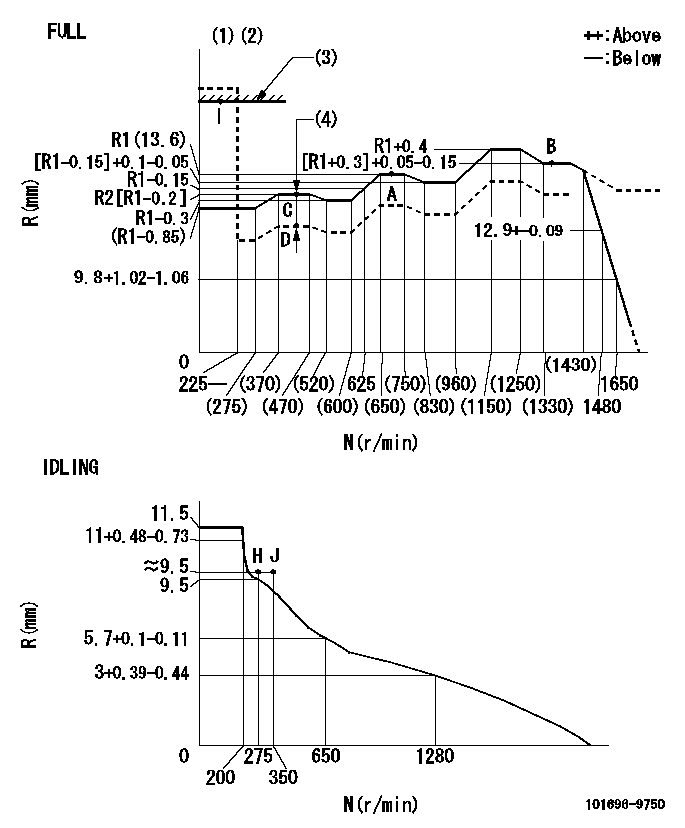
Test data Ex:
Governor adjustment

N:Pump speed
R:Rack position (mm)
(1)Torque cam stamping: T1
(2)Tolerance for racks not indicated: +-0.05mm.
(3)RACK LIMIT
(4)Boost compensator stroke: BCL
----------
T1=M43 BCL=1.8+-0.1mm
----------
----------
T1=M43 BCL=1.8+-0.1mm
----------
Speed control lever angle

F:Full speed
I:Idle
(1)Use the hole at R = aa
(2)Stopper bolt setting
----------
aa=36mm
----------
a=26.5deg+-5deg b=39deg+-3deg
----------
aa=36mm
----------
a=26.5deg+-5deg b=39deg+-3deg
Stop lever angle

N:Pump normal
S:Stop the pump.
(1)Use the pin at R = aa
----------
aa=42mm
----------
a=40deg+-5deg b=27deg+-5deg
----------
aa=42mm
----------
a=40deg+-5deg b=27deg+-5deg
Timing setting

(1)Pump vertical direction
(2)Position of timer's threaded hole at the No. 1 cylinder's beginning of injection
(3)-
(4)-
----------
----------
a=(60deg)
----------
----------
a=(60deg)
Information:
Cooling Systems with Larger Capacities
Adding the SCA to Conventional Coolant/Antifreeze at the Initial Fill
Note: When the coolant system is first filled, the SCA is not required to be used with Cat DEAC or with fully formulated coolants that meet the "ASTM D6210" specification.Note: Do not exceed the six percent maximum concentration. Check the concentration of SCA with a SCA test kit, or check the concentration of SCA with Cat S O S coolant analysis.Commercial heavy-duty coolant/antifreeze that meets only the "ASTM D4985" specification WILL require adding supplemental coolant additive at the initial fill. Read the label or the instructions that are provided by the manufacturer of the commercial heavy-duty coolant/antifreeze.Use the equation that is in Table 3 as a guideline in order to aid in determining the amount of SCA that is required when the cooling system is initially filled with fluids that only meet the "ASTM D4985" specification.Note: When adding SCA at initial fill to a coolant/antifreeze that only meets the "ASTM D4985", ensure the SCA is compatible with the antifreeze/coolant. For example, a HOAT coolant that meets the "ASTM D4985" specification may not be compatible with an SCA designed for use with conventional coolants. It is the responsibility of the coolant manufacturer to provide sources of compatible SCAs. It is the responsibility of the coolant manufacturer and SCA manufacturer to demonstrate a positive influence on reducing cavitation corrosion in an operating diesel engineNote: When adding SCA at initial fill to a coolant/antifreeze that only meets the "ASTM D4985", it is a collective responsibility of the user, coolant manufacturer, and SCA manufacturer to ensure the SCA is compatible with the antifreeze/coolant based on the recommendations provided by the coolant manufacturer and SCA manufacturer. One of the test methods required to be used to help ensure SCA compatibility with the antifreeze/coolant concentrate is "ASTM D5828-97". 6% SCA in the solution that is 60 parts antifreeze/coolant of interest, 34 parts water, and 6 parts SCA must have no more than 0.1 mL of formed insolubles. 12% SCA in a solution that is 60 parts antifreeze/coolant of interest, 28 parts water, and 12 parts SCA must have no more than 2 mL of formed insolubles. The SCA manufacturer is responsible for ensuring their SCA is compatible with water meeting the “Caterpillar Minimum Acceptable Water Quality Requirements” as found in this "Special Publication, and as found in "ASTM D6210-06", Table X1.1.
Table 3
Equation for Adding the Cat SCA to Conventional Coolant/Antifreeze at the Initial Fill
V × 0.045 = X
V is the total volume of the cooling system.
X is the amount of Cat SCA that is required. Table 4 is an example for using the equation that is in Table 3.
Table 4
Example of the Equation for Adding the Cat SCA to Conventional Coolant/Antifreeze at the Initial Fill
Total Volume of the Cooling System (V) Multiplication
Factor Amount of Cat SCA that is Required (X)
190 L
(50 US gal) × 0.045 8.5 L
(2.3 US gal) Adding the SCA to Conventional Coolant/Antifreeze for Maintenance
Conventional heavy-duty coolant/antifreeze of

