Information injection-pump assembly
ZEXEL
101696-9620
1016969620
NISSAN-DIESEL
16713Z6617
16713z6617

Rating:
Cross reference number
ZEXEL
101696-9620
1016969620
NISSAN-DIESEL
16713Z6617
16713z6617
Zexel num
Bosch num
Firm num
Name
101696-9620
16713Z6617 NISSAN-DIESEL
INJECTION-PUMP ASSEMBLY
FE6T * K
FE6T * K
Calibration Data:
Adjustment conditions
Test oil
1404 Test oil ISO4113 or {SAEJ967d}
1404 Test oil ISO4113 or {SAEJ967d}
Test oil temperature
degC
40
40
45
Nozzle and nozzle holder
105780-8140
Bosch type code
EF8511/9A
Nozzle
105780-0000
Bosch type code
DN12SD12T
Nozzle holder
105780-2080
Bosch type code
EF8511/9
Opening pressure
MPa
17.2
Opening pressure
kgf/cm2
175
Injection pipe
Outer diameter - inner diameter - length (mm) mm 6-2-600
Outer diameter - inner diameter - length (mm) mm 6-2-600
Overflow valve
134424-1520
Overflow valve opening pressure
kPa
162
147
177
Overflow valve opening pressure
kgf/cm2
1.65
1.5
1.8
Tester oil delivery pressure
kPa
157
157
157
Tester oil delivery pressure
kgf/cm2
1.6
1.6
1.6
Direction of rotation (viewed from drive side)
Right R
Right R
Injection timing adjustment
Direction of rotation (viewed from drive side)
Right R
Right R
Injection order
1-4-2-6-
3-5
Pre-stroke
mm
3.9
3.85
3.95
Beginning of injection position
Drive side NO.1
Drive side NO.1
Difference between angles 1
Cal 1-4 deg. 60 59.5 60.5
Cal 1-4 deg. 60 59.5 60.5
Difference between angles 2
Cyl.1-2 deg. 120 119.5 120.5
Cyl.1-2 deg. 120 119.5 120.5
Difference between angles 3
Cal 1-6 deg. 180 179.5 180.5
Cal 1-6 deg. 180 179.5 180.5
Difference between angles 4
Cal 1-3 deg. 240 239.5 240.5
Cal 1-3 deg. 240 239.5 240.5
Difference between angles 5
Cal 1-5 deg. 300 299.5 300.5
Cal 1-5 deg. 300 299.5 300.5
Injection quantity adjustment
Adjusting point
-
Rack position
13.1
Pump speed
r/min
700
700
700
Average injection quantity
mm3/st.
94.8
92.8
96.8
Max. variation between cylinders
%
0
-3.5
3.5
Basic
*
Fixing the rack
*
Standard for adjustment of the maximum variation between cylinders
*
Injection quantity adjustment_02
Adjusting point
H
Rack position
9.5+-0.5
Pump speed
r/min
275
275
275
Average injection quantity
mm3/st.
9.5
7.7
11.3
Max. variation between cylinders
%
0
-10
10
Fixing the rack
*
Standard for adjustment of the maximum variation between cylinders
*
Injection quantity adjustment_03
Adjusting point
A
Rack position
R1(13.1)
Pump speed
r/min
700
700
700
Average injection quantity
mm3/st.
94.8
93.8
95.8
Basic
*
Fixing the lever
*
Boost pressure
kPa
26.7
26.7
Boost pressure
mmHg
200
200
Injection quantity adjustment_04
Adjusting point
B
Rack position
R1
Pump speed
r/min
1400
1400
1400
Average injection quantity
mm3/st.
100.4
97.2
103.6
Fixing the lever
*
Boost pressure
kPa
26.7
26.7
Boost pressure
mmHg
200
200
Injection quantity adjustment_05
Adjusting point
C
Rack position
R2[R1-0.
2]
Pump speed
r/min
400
400
400
Average injection quantity
mm3/st.
76.6
73.4
79.8
Fixing the lever
*
Boost pressure
kPa
26.7
26.7
Boost pressure
mmHg
200
200
Injection quantity adjustment_06
Adjusting point
D
Rack position
R2-1.05
Pump speed
r/min
400
400
400
Average injection quantity
mm3/st.
57.7
55.7
59.7
Fixing the lever
*
Boost pressure
kPa
0
0
0
Boost pressure
mmHg
0
0
0
Injection quantity adjustment_07
Adjusting point
I
Rack position
-
Pump speed
r/min
150
150
150
Average injection quantity
mm3/st.
85
85
105
Fixing the lever
*
Boost pressure
kPa
0
0
0
Boost pressure
mmHg
0
0
0
Rack limit
*
Boost compensator adjustment
Pump speed
r/min
400
400
400
Rack position
R2-1.05
Boost pressure
kPa
6.7
5.4
8
Boost pressure
mmHg
50
40
60
Boost compensator adjustment_02
Pump speed
r/min
400
400
400
Rack position
R2[R1-0.
2]
Boost pressure
kPa
13.3
13.3
13.3
Boost pressure
mmHg
100
100
100
Timer adjustment
Pump speed
r/min
1170--
Advance angle
deg.
0
0
0
Remarks
Start
Start
Timer adjustment_02
Pump speed
r/min
1120
Advance angle
deg.
0.5
Timer adjustment_03
Pump speed
r/min
1400
Advance angle
deg.
3
2.5
3.5
Remarks
Finish
Finish
Test data Ex:
Governor adjustment
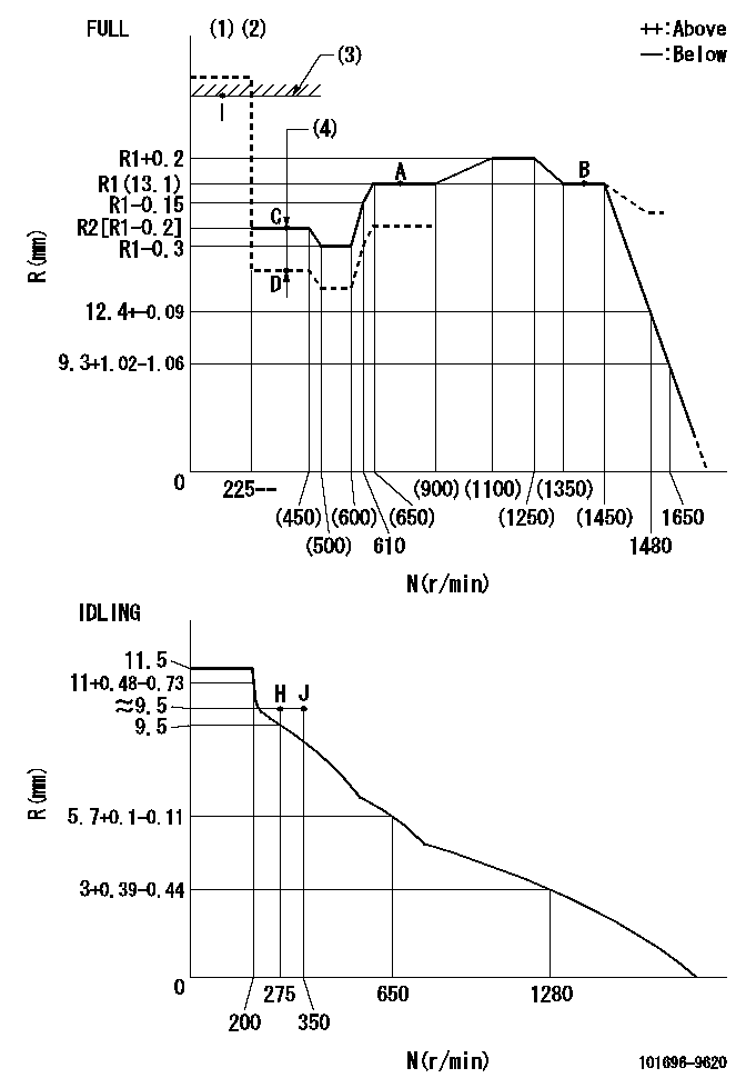
N:Pump speed
R:Rack position (mm)
(1)Torque cam stamping: T1
(2)Tolerance for racks not indicated: +-0.05mm.
(3)RACK LIMIT
(4)Boost compensator stroke: BCL
----------
T1=G99 BCL=1.05+-0.1mm
----------
----------
T1=G99 BCL=1.05+-0.1mm
----------
Speed control lever angle

F:Full speed
I:Idle
(1)Use the hole at R = aa
(2)Stopper bolt setting
----------
aa=36mm
----------
a=26.5deg+-5deg b=(38deg)+-3deg
----------
aa=36mm
----------
a=26.5deg+-5deg b=(38deg)+-3deg
Stop lever angle

N:Pump normal
S:Stop the pump.
(1)Use the pin at R = aa
----------
aa=42mm
----------
a=40deg+-5deg b=27deg+-5deg
----------
aa=42mm
----------
a=40deg+-5deg b=27deg+-5deg
Timing setting

(1)Pump vertical direction
(2)Position of timer's threaded hole at No 1 cylinder's beginning of injection
(3)-
(4)-
----------
----------
a=(60deg)
----------
----------
a=(60deg)
Information:
Illustration 1 g00293000
Junction Box-ETR Switchgear Required (OP, WT, OS)
(1) Electronic speed switch ("ESS").
(2) Lockwire (for seal screw plugs).
(3) Identification foil.
(4) Diode ("D4").
(5) Diode ("D3").
(6) Slave relay ("SR1").
(7) Slave relay ("SR2").
(8) Emergency stop switch ("ES").
(9) Circuit breakers.
Illustration 2 g00293001
Junction Box-ETS Switchgear Not Required (OP, WT, OS)
(1) Electronic speed switch ("ESS").
(2) Lockwire (for seal screw plugs).
(3) Identification foil.
(4) Slave relay ("SR1").
(5) Emergency stop switch ("ES").
(6) Time delay relay ("TD1").
(7) Start-stop switch ("SSS").
Illustration 3 g00293002
Junction Box-ETS Switchgear Required (OP, WT, OS)
(1) Electronic speed switch ("ESS").
(2) Lockwire (for seal screw plugs).
(3) Slave relay ("SR1").
(4) Emergency stop switch ("ES").
(5) Time delay relay ("TD1").
(6) Circuit breakers.
(7) Engine mounted start-stop switch ("EMSS."
Illustration 4 g00293003
Junction Box-ETS Switchgear Not Required (OP, WT)
(1) Time delay relay ("TD2").
(2) Emergency stop switch ("ES").
(3) Identification foil.
(4) Slave relay ("SR1").
(5) Slave relay ("SR2").
(6) Time delay relay ("TD1").
(7) Circuit breakers.
Illustration 5 g00293004
Junction Box With Start-stop Switch ("SSS")
(1) Emergency stop switch ("ES").
(2) Circuit breaker reset buttons.
(3) Start-stop switch ("SSS").
Illustration 6 g00293005
(1) Power distribution box. (2) Circuit breaker reset button.
Illustration 7 g00293006
(1) Hour meter.
Illustration 8 g00293007
(1) Air starting motor. (2) Air starting valve. (3) Air supply pipe.
Have questions with 101696-9620?
Group cross 101696-9620 ZEXEL
Nissan-Diesel
101696-9620
16713Z6617
INJECTION-PUMP ASSEMBLY
FE6T
FE6T