Information injection-pump assembly
BOSCH
9 400 616 152
9400616152
ZEXEL
101696-9570
1016969570
NISSAN-DIESEL
16713Z6408
16713z6408
Rating:
Include in #1:
106651-2472
as _
Cross reference number
BOSCH
9 400 616 152
9400616152
ZEXEL
101696-9570
1016969570
NISSAN-DIESEL
16713Z6408
16713z6408
Zexel num
Bosch num
Firm num
Name
101696-9570
9 400 616 152
16713Z6408 NISSAN-DIESEL
INJECTION-PUMP ASSEMBLY
FE6T K
FE6T K
Calibration Data:
Adjustment conditions
Test oil
1404 Test oil ISO4113 or {SAEJ967d}
1404 Test oil ISO4113 or {SAEJ967d}
Test oil temperature
degC
40
40
45
Nozzle and nozzle holder
105780-8140
Bosch type code
EF8511/9A
Nozzle
105780-0000
Bosch type code
DN12SD12T
Nozzle holder
105780-2080
Bosch type code
EF8511/9
Opening pressure
MPa
17.2
Opening pressure
kgf/cm2
175
Injection pipe
Outer diameter - inner diameter - length (mm) mm 6-2-600
Outer diameter - inner diameter - length (mm) mm 6-2-600
Overflow valve
131424-1520
Overflow valve opening pressure
kPa
157
123
191
Overflow valve opening pressure
kgf/cm2
1.6
1.25
1.95
Tester oil delivery pressure
kPa
157
157
157
Tester oil delivery pressure
kgf/cm2
1.6
1.6
1.6
Direction of rotation (viewed from drive side)
Right R
Right R
Injection timing adjustment
Direction of rotation (viewed from drive side)
Right R
Right R
Injection order
1-4-2-6-
3-5
Pre-stroke
mm
3.4
3.35
3.45
Beginning of injection position
Drive side NO.1
Drive side NO.1
Difference between angles 1
Cal 1-4 deg. 60 59.5 60.5
Cal 1-4 deg. 60 59.5 60.5
Difference between angles 2
Cyl.1-2 deg. 120 119.5 120.5
Cyl.1-2 deg. 120 119.5 120.5
Difference between angles 3
Cal 1-6 deg. 180 179.5 180.5
Cal 1-6 deg. 180 179.5 180.5
Difference between angles 4
Cal 1-3 deg. 240 239.5 240.5
Cal 1-3 deg. 240 239.5 240.5
Difference between angles 5
Cal 1-5 deg. 300 299.5 300.5
Cal 1-5 deg. 300 299.5 300.5
Injection quantity adjustment
Adjusting point
-
Rack position
14
Pump speed
r/min
550
550
550
Average injection quantity
mm3/st.
84.8
82.8
86.8
Max. variation between cylinders
%
0
-3.5
3.5
Basic
*
Fixing the rack
*
Standard for adjustment of the maximum variation between cylinders
*
Injection quantity adjustment_02
Adjusting point
-
Rack position
9.7+-0.5
Pump speed
r/min
275
275
275
Average injection quantity
mm3/st.
9.5
7.7
11.3
Max. variation between cylinders
%
0
-10
10
Fixing the rack
*
Standard for adjustment of the maximum variation between cylinders
*
Remarks
Adjust only variation between cylinders; adjust governor according to governor specifications.
Adjust only variation between cylinders; adjust governor according to governor specifications.
Injection quantity adjustment_03
Adjusting point
A
Rack position
R1(14)
Pump speed
r/min
550
550
550
Average injection quantity
mm3/st.
84.8
83.8
85.8
Basic
*
Fixing the lever
*
Boost pressure
kPa
25.3
25.3
Boost pressure
mmHg
190
190
Injection quantity adjustment_04
Adjusting point
B
Rack position
R1-0.1
Pump speed
r/min
850
850
850
Average injection quantity
mm3/st.
91.9
88.7
95.1
Fixing the lever
*
Boost pressure
kPa
25.3
25.3
Boost pressure
mmHg
190
190
Injection quantity adjustment_05
Adjusting point
C
Rack position
R1-0.3
Pump speed
r/min
1400
1400
1400
Average injection quantity
mm3/st.
96.5
93.3
99.7
Fixing the lever
*
Boost pressure
kPa
25.3
25.3
Boost pressure
mmHg
190
190
Injection quantity adjustment_06
Adjusting point
D
Rack position
R2(12.3)
Pump speed
r/min
550
550
550
Average injection quantity
mm3/st.
59.7
58.7
60.7
Fixing the lever
*
Boost pressure
kPa
0
0
0
Boost pressure
mmHg
0
0
0
Injection quantity adjustment_07
Adjusting point
I
Rack position
-
Pump speed
r/min
150
150
150
Average injection quantity
mm3/st.
83.5
83.5
103.5
Fixing the lever
*
Boost pressure
kPa
0
0
0
Boost pressure
mmHg
0
0
0
Rack limit
*
Boost compensator adjustment
Pump speed
r/min
550
550
550
Rack position
R2(12.3)
Boost pressure
kPa
4
2.7
5.3
Boost pressure
mmHg
30
20
40
Boost compensator adjustment_02
Pump speed
r/min
550
550
550
Rack position
R1(14)
Boost pressure
kPa
12
12
12
Boost pressure
mmHg
90
90
90
Timer adjustment
Pump speed
r/min
1170--
Advance angle
deg.
0
0
0
Remarks
Start
Start
Timer adjustment_02
Pump speed
r/min
1120
Advance angle
deg.
0.5
Timer adjustment_03
Pump speed
r/min
1400
Advance angle
deg.
2
1.5
2.5
Remarks
Finish
Finish
Test data Ex:
Governor adjustment
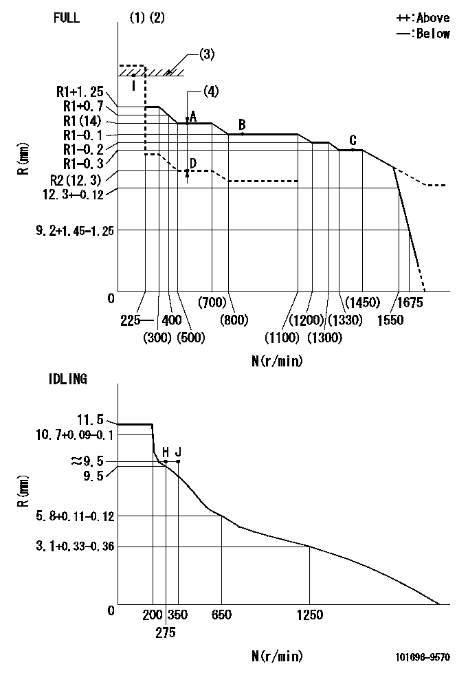
N:Pump speed
R:Rack position (mm)
(1)Torque cam stamping: T1
(2)Tolerance for racks not indicated: +-0.05mm.
(3)RACK LIMIT
(4)Boost compensator stroke: BCL
----------
T1=C44 BCL=(1.7)+-0.1mm
----------
----------
T1=C44 BCL=(1.7)+-0.1mm
----------
Speed control lever angle

F:Full speed
I:Idle
(1)Stopper bolt set position 'H'
----------
----------
a=26.5deg+-5deg b=(42deg)+-3deg
----------
----------
a=26.5deg+-5deg b=(42deg)+-3deg
Stop lever angle

N:Pump normal
S:Stop the pump.
----------
----------
a=20deg+-5deg b=40deg+-5deg
----------
----------
a=20deg+-5deg b=40deg+-5deg
Timing setting

(1)Pump vertical direction
(2)Position of timer's threaded hole at No 1 cylinder's beginning of injection
(3)-
(4)-
----------
----------
a=(60deg)
----------
----------
a=(60deg)
Information:
Illustration 8 g00281837
Circuit breaker
(1) Reset button
(2) Disc in open position
(3) Contacts
(4) Disc in closed position
(5) Battery circuit terminals A circuit breaker is a switch that opens the circuit if the current in the electrical system is higher than the rating of the circuit breaker.A metal disc that is controlled with heat and a contact (3) will complete the circuit through the circuit breaker. If the current in the electrical system is too high, the metal disc becomes too hot. The heat causes a distortion of the metal disc which opens the contacts (2). Open contacts break the circuit. A circuit breaker that is open can be reset after the circuit breaker cools. Push the reset button (1) in order to close the contacts (4) and reset the circuit breaker.
Find and correct the problem that causes the circuit breaker to open.Correcting the problem before running the engine will help prevent damage to the circuit components caused by too much current.
Air Shutoff Solenoid (ASOS)
Illustration 9 g00281839
Air shutoff (Typical example)
(1) Air transfer pipe
(2) Valve assembly
(3) Shutoff shaft
(4) Governor control shaft
(5) Air shutoff solenoid
(6) O-ring seal
(7) Diode assembly
Illustration 10 g00293067
(5) Air shutoff solenoid that is mounted in the air intake pipe.
The air shutoff solenoid (5) is located in the air inlet system on the top of the engine. When the air shutoff solenoid ("ASOS") is energized, the inlet air to the engine is mechanically shut off. The ASOS can be energized in the following two ways:
The ASOS is energized by the overspeed switch (OS).
The ASOS is energized by the emergency stop switch (ES).Fuel Solenoid (FS)
Illustration 11 g00281970
Fuel solenoid (Typical example)
(1) Diode assembly
(2) Spring
(3) Governor drive
(4) Fuel solenoid
(5) Shaft
Illustration 12 g00293070
(4) Fuel solenoid (FS) that is mounted on the governor.
The fuel solenoid (FS) (4) is located on the governor or on the fuel injection pump of the engine. When the FS is energized, the spring (2) and the shaft (5) will cause the fuel rack to move directly or the fuel rack will move through the governor drive to the FUEL ON position. The FS must remain energized or the fuel flow will be stopped to the engine. 2301A Electric Governor Control
Illustration 13 g00293071
(1) 2301A Electric Governor Speed Control
Illustration 14 g00293069
Electric governor actuator (EGA) (2) and fuel solenoid (FS) (3). The components are mounted on the top of the engine.
The 2301A Electric Governor Control system consists of the following components:
2301A Control
Actuator (EGA)
Magnetic pickup (MPU)The 2301A Electric Governor Control system provides precision engine speed control. The 2301A Control constantly monitors the engine rpm. The control makes the necessary corrections to the engine fuel setting through an actuator that is connected to the fuel system.The engine rpm is measured by the magnetic pickup ("MU"). The magnetic pickup makes an AC voltage that is sent to the 2301A Control. The 2301A Control then sends a DC voltage signal to the actuator in order to adjust the fuel flow.The actuator changes the electrical signal from the 2301A Control to a mechanical output. The mechanical output of the actuator causes the linkage from the actuator
Have questions with 101696-9570?
Group cross 101696-9570 ZEXEL
Nissan-Diesel
Nissan-Diesel
101696-9570
9 400 616 152
16713Z6408
INJECTION-PUMP ASSEMBLY
FE6T
FE6T