Information injection-pump assembly
BOSCH
9 400 616 151
9400616151
ZEXEL
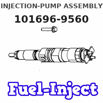
101696-9560
1016969560
NISSAN-DIESEL
16713Z6405
16713z6405
Rating:
Include in #1:
106661-2181
as _
Cross reference number
BOSCH
9 400 616 151
9400616151
ZEXEL
101696-9560
1016969560
NISSAN-DIESEL
16713Z6405
16713z6405
Zexel num
Bosch num
Firm num
Name
101696-9560
9 400 616 151
16713Z6405 NISSAN-DIESEL
INJECTION-PUMP ASSEMBLY
FE6T K
FE6T K
Calibration Data:
Adjustment conditions
Test oil
1404 Test oil ISO4113 or {SAEJ967d}
1404 Test oil ISO4113 or {SAEJ967d}
Test oil temperature
degC
40
40
45
Nozzle and nozzle holder
105780-8140
Bosch type code
EF8511/9A
Nozzle
105780-0000
Bosch type code
DN12SD12T
Nozzle holder
105780-2080
Bosch type code
EF8511/9
Opening pressure
MPa
17.2
Opening pressure
kgf/cm2
175
Injection pipe
Outer diameter - inner diameter - length (mm) mm 6-2-600
Outer diameter - inner diameter - length (mm) mm 6-2-600
Overflow valve
131424-1520
Overflow valve opening pressure
kPa
157
123
191
Overflow valve opening pressure
kgf/cm2
1.6
1.25
1.95
Tester oil delivery pressure
kPa
157
157
157
Tester oil delivery pressure
kgf/cm2
1.6
1.6
1.6
Direction of rotation (viewed from drive side)
Right R
Right R
Injection timing adjustment
Direction of rotation (viewed from drive side)
Right R
Right R
Injection order
1-4-2-6-
3-5
Pre-stroke
mm
3.4
3.35
3.45
Beginning of injection position
Drive side NO.1
Drive side NO.1
Difference between angles 1
Cal 1-4 deg. 60 59.5 60.5
Cal 1-4 deg. 60 59.5 60.5
Difference between angles 2
Cyl.1-2 deg. 120 119.5 120.5
Cyl.1-2 deg. 120 119.5 120.5
Difference between angles 3
Cal 1-6 deg. 180 179.5 180.5
Cal 1-6 deg. 180 179.5 180.5
Difference between angles 4
Cal 1-3 deg. 240 239.5 240.5
Cal 1-3 deg. 240 239.5 240.5
Difference between angles 5
Cal 1-5 deg. 300 299.5 300.5
Cal 1-5 deg. 300 299.5 300.5
Injection quantity adjustment
Adjusting point
-
Rack position
14
Pump speed
r/min
550
550
550
Average injection quantity
mm3/st.
84.8
82.8
86.8
Max. variation between cylinders
%
0
-3.5
3.5
Basic
*
Fixing the rack
*
Standard for adjustment of the maximum variation between cylinders
*
Injection quantity adjustment_02
Adjusting point
-
Rack position
9.7+-0.5
Pump speed
r/min
275
275
275
Average injection quantity
mm3/st.
9.5
7.7
11.3
Max. variation between cylinders
%
0
-10
10
Fixing the rack
*
Standard for adjustment of the maximum variation between cylinders
*
Remarks
Adjust only variation between cylinders; adjust governor according to governor specifications.
Adjust only variation between cylinders; adjust governor according to governor specifications.
Injection quantity adjustment_03
Adjusting point
A
Rack position
R1(14)
Pump speed
r/min
550
550
550
Average injection quantity
mm3/st.
84.8
83.8
85.8
Basic
*
Fixing the lever
*
Boost pressure
kPa
25.3
25.3
Boost pressure
mmHg
190
190
Injection quantity adjustment_04
Adjusting point
B
Rack position
R1-0.1
Pump speed
r/min
850
850
850
Average injection quantity
mm3/st.
91.9
88.7
95.1
Fixing the lever
*
Boost pressure
kPa
25.3
25.3
Boost pressure
mmHg
190
190
Injection quantity adjustment_05
Adjusting point
C
Rack position
R1-0.3
Pump speed
r/min
1400
1400
1400
Average injection quantity
mm3/st.
96.5
93.3
99.7
Fixing the lever
*
Boost pressure
kPa
25.3
25.3
Boost pressure
mmHg
190
190
Injection quantity adjustment_06
Adjusting point
D
Rack position
R2(12.3)
Pump speed
r/min
550
550
550
Average injection quantity
mm3/st.
59.7
58.7
60.7
Fixing the lever
*
Boost pressure
kPa
0
0
0
Boost pressure
mmHg
0
0
0
Injection quantity adjustment_07
Adjusting point
I
Rack position
-
Pump speed
r/min
150
150
150
Average injection quantity
mm3/st.
83.5
83.5
103.5
Fixing the lever
*
Boost pressure
kPa
0
0
0
Boost pressure
mmHg
0
0
0
Rack limit
*
Boost compensator adjustment
Pump speed
r/min
550
550
550
Rack position
R2(12.3)
Boost pressure
kPa
4
2.7
5.3
Boost pressure
mmHg
30
20
40
Boost compensator adjustment_02
Pump speed
r/min
550
550
550
Rack position
R1(14)
Boost pressure
kPa
12
12
12
Boost pressure
mmHg
90
90
90
Timer adjustment
Pump speed
r/min
1170--
Advance angle
deg.
0
0
0
Remarks
Start
Start
Timer adjustment_02
Pump speed
r/min
1120
Advance angle
deg.
0.5
Timer adjustment_03
Pump speed
r/min
1400
Advance angle
deg.
2
1.5
2.5
Remarks
Finish
Finish
Test data Ex:
Governor adjustment
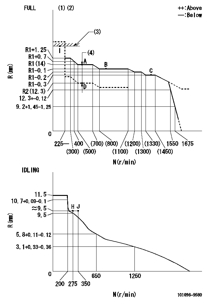
N:Pump speed
R:Rack position (mm)
(1)Torque cam stamping: T1
(2)Tolerance for racks not indicated: +-0.05mm.
(3)RACK LIMIT
(4)Boost compensator stroke: BCL
----------
T1=C44 BCL=(1.7)+-0.1mm
----------
----------
T1=C44 BCL=(1.7)+-0.1mm
----------
Speed control lever angle

F:Full speed
I:Idle
(1)Stopper bolt set position 'H'
----------
----------
a=26.5deg+-5deg b=(42deg)+-3deg
----------
----------
a=26.5deg+-5deg b=(42deg)+-3deg
Stop lever angle

N:Pump normal
S:Stop the pump.
----------
----------
a=20deg+-5deg b=40deg+-5deg
----------
----------
a=20deg+-5deg b=40deg+-5deg
Timing setting

(1)Pump vertical direction
(2)Position of timer's threaded hole at No 1 cylinder's beginning of injection
(3)-
(4)-
----------
----------
a=(60deg)
----------
----------
a=(60deg)
Information:
Introduction
Do not perform any procedure that is outlined in the Special Instruction until the entire instruction has been read and understood.Check Valve Torque
Care must be taken to ensure that fluids are contained during performance of inspection, maintenance, testing, adjusting, and repair of the product. Be prepared to collect the fluid with suitable containers before opening any compartment or disassembling any component containing fluids.Refer to Special Publication, NENG2500, "Dealer Service Tool Catalog" for tools and supplies suitable to collect and contain fluids on Cat products.Dispose of all fluids according to local regulations and mandates.
The check valves that are located within the fuel pressure regulator group are sensitive to assembly torque. In order to eliminate the risk of valve distortion, torque the check valves to 28 3 N m (21 2 lb ft). Refer to Table 1 for the check valve part numbers that required the torque that is listed above.
Table 1
Part Number Description
327-0376 Check Valve Gp
327-4448 Check Valve Gp
281-2725 Check Valve Gp
282-1915 Check Valve Gp
228-7381 Check Valve Gp
327-8044 Check Valve Gp
Have questions with 101696-9560?
Group cross 101696-9560 ZEXEL
Nissan-Diesel
Nissan-Diesel
101696-9560
9 400 616 151
16713Z6405
INJECTION-PUMP ASSEMBLY
FE6T
FE6T