Information injection-pump assembly
BOSCH
9 400 610 809
9400610809
ZEXEL
101696-9550
1016969550
NISSAN-DIESEL
16713Z6602
16713z6602
Rating:
Service parts 101696-9550 INJECTION-PUMP ASSEMBLY:
1.
_
7.
COUPLING PLATE
8.
_
9.
_
11.
Nozzle and Holder
16600-Z5570
12.
Open Pre:MPa(Kqf/cm2)
21.6{220}
15.
NOZZLE SET
Cross reference number
BOSCH
9 400 610 809
9400610809
ZEXEL
101696-9550
1016969550
NISSAN-DIESEL
16713Z6602
16713z6602
Zexel num
Bosch num
Firm num
Name
101696-9550
9 400 610 809
16713Z6602 NISSAN-DIESEL
INJECTION-PUMP ASSEMBLY
FE6T K 14BE INJECTION PUMP ASSY PE6A PE
FE6T K 14BE INJECTION PUMP ASSY PE6A PE
Calibration Data:
Adjustment conditions
Test oil
1404 Test oil ISO4113 or {SAEJ967d}
1404 Test oil ISO4113 or {SAEJ967d}
Test oil temperature
degC
40
40
45
Nozzle and nozzle holder
105780-8140
Bosch type code
EF8511/9A
Nozzle
105780-0000
Bosch type code
DN12SD12T
Nozzle holder
105780-2080
Bosch type code
EF8511/9
Opening pressure
MPa
17.2
Opening pressure
kgf/cm2
175
Injection pipe
Outer diameter - inner diameter - length (mm) mm 6-2-600
Outer diameter - inner diameter - length (mm) mm 6-2-600
Overflow valve
131424-1520
Overflow valve opening pressure
kPa
157
123
191
Overflow valve opening pressure
kgf/cm2
1.6
1.25
1.95
Tester oil delivery pressure
kPa
157
157
157
Tester oil delivery pressure
kgf/cm2
1.6
1.6
1.6
Direction of rotation (viewed from drive side)
Right R
Right R
Injection timing adjustment
Direction of rotation (viewed from drive side)
Right R
Right R
Injection order
1-4-2-6-
3-5
Pre-stroke
mm
3.4
3.35
3.45
Beginning of injection position
Drive side NO.1
Drive side NO.1
Difference between angles 1
Cal 1-4 deg. 60 59.5 60.5
Cal 1-4 deg. 60 59.5 60.5
Difference between angles 2
Cyl.1-2 deg. 120 119.5 120.5
Cyl.1-2 deg. 120 119.5 120.5
Difference between angles 3
Cal 1-6 deg. 180 179.5 180.5
Cal 1-6 deg. 180 179.5 180.5
Difference between angles 4
Cal 1-3 deg. 240 239.5 240.5
Cal 1-3 deg. 240 239.5 240.5
Difference between angles 5
Cal 1-5 deg. 300 299.5 300.5
Cal 1-5 deg. 300 299.5 300.5
Injection quantity adjustment
Adjusting point
-
Rack position
12.5
Pump speed
r/min
1500
1500
1500
Average injection quantity
mm3/st.
83.7
82.1
85.3
Max. variation between cylinders
%
0
-3.5
3.5
Basic
*
Fixing the rack
*
Standard for adjustment of the maximum variation between cylinders
*
Injection quantity adjustment_02
Adjusting point
H
Rack position
9.5+-0.5
Pump speed
r/min
300
300
300
Average injection quantity
mm3/st.
9.5
7.7
11.3
Max. variation between cylinders
%
0
-10
10
Fixing the rack
*
Standard for adjustment of the maximum variation between cylinders
*
Injection quantity adjustment_03
Adjusting point
A
Rack position
R1(12.5)
Pump speed
r/min
1500
1500
1500
Average injection quantity
mm3/st.
83.7
82.7
84.7
Basic
*
Fixing the lever
*
Injection quantity adjustment_04
Adjusting point
B
Rack position
R1-0.55
Pump speed
r/min
900
900
900
Average injection quantity
mm3/st.
68.7
66.7
70.7
Fixing the lever
*
Injection quantity adjustment_05
Adjusting point
I
Rack position
-
Pump speed
r/min
150
150
150
Average injection quantity
mm3/st.
85
85
105
Fixing the lever
*
Rack limit
*
Timer adjustment
Pump speed
r/min
1050--
Advance angle
deg.
0
0
0
Remarks
Start
Start
Timer adjustment_02
Pump speed
r/min
1000
Advance angle
deg.
0.5
Timer adjustment_03
Pump speed
r/min
1500
Advance angle
deg.
2
1.5
2.5
Remarks
Finish
Finish
Test data Ex:
Governor adjustment
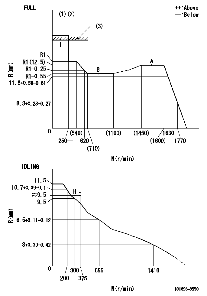
N:Pump speed
R:Rack position (mm)
(1)Torque cam stamping: T1
(2)Tolerance for racks not indicated: +-0.05mm.
(3)RACK LIMIT
----------
T1=L92
----------
----------
T1=L92
----------
Speed control lever angle

F:Full speed
I:Idle
(1)Use the hole at R = aa
(2)Stopper bolt set position 'H'
----------
aa=100mm
----------
a=26.5deg+-5deg b=39deg+-3deg
----------
aa=100mm
----------
a=26.5deg+-5deg b=39deg+-3deg
Stop lever angle
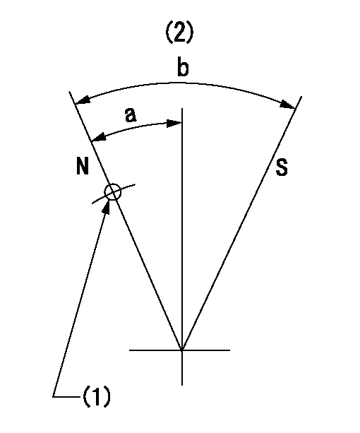
N:Pump normal
S:Stop the pump.
(1)Use the pin at R = aa
(2)Normal
----------
aa=42mm
----------
a=27deg+-5deg b=40deg+-5deg
----------
aa=42mm
----------
a=27deg+-5deg b=40deg+-5deg
Timing setting

(1)Pump vertical direction
(2)Position of timer's threaded hole at No 1 cylinder's beginning of injection
(3)-
(4)-
----------
----------
a=(60deg)
----------
----------
a=(60deg)
Information:
Introduction
Note: Do not perform any procedure in this Special Instruction until the information has been read and understood.Injector Wiring Harness Kit
The new 141-7060 Injector Wiring Harness Kit is available to repair the connectors on the 122-8835 Wiring Harness Assembly or the 133-3745 Wiring Harness Assembly . The connectors on the wiring harness assembly connect to the Hydraulic Electronic Unit Injectors (HEUI) in the above Caterpillar Truck Engines. Each injector wiring harness kit includes:
one connector
two barrel splices
two pieces of heat shrink tubingInstallation Of The 141-7060 Injector Wiring Harness Kit
Carefully remove the valve cover from the engine. Avoid damaging the gasket on the valve cover.
Remove the damaged connector from the HEUI injector solenoid.
Cut the damaged connector from the HEUI injector wiring harness. A length of 31.8 mm (1.25 inch) should remain from the heat shrink tubing on one of the harness wires. A length of 19.1 mm (0.75 inch) should remain from the heat shrink tubing on the other harness wire.Note: DO NOT allow the removed insulation to fall into the cylinder head assembly. DO NOT allow the removed insulation to fall into the open passages of the oil sump.
Remove approximately 8 mm (0.3 inch) of the insulation from the two harness wires.Note: Remove only enough insulation in order to allow the harness wires to seat into the new barrel splice from the injector wiring harness kit.
Remove the two pieces of the heat shrink tubing from the injector wiring harness kit.
Slip the heat shrink tubing from the injector wiring harness kit over the ends of the HEUI injector wiring harness wires.Note: The heat shrink tubing must be pushed far enough onto the harness wires so that the heat shrink tubing will not be cut when crimping the barrel splices. DO NOT crimp through the heat shrink tubing. Crimping through the heat shrink tubing will cause damage.
Remove the replacement connector from the injector wiring harness kit.
Install the replacement connector on the HEUI injector wiring harness wires.
Crimp the two barrel splices to the HEUI injector wiring harness wires.
Move the heat shrink tubing over the exposed barrel splices. Center the barrel splices in the heat shrink tubing.
Use a heat gun to heat the heat shrink tubing. Apply heat until the tubing shrinks evenly around the barrel splices.Note: DO NOT overheat the heat shrink tubing. Damage to the heat shrink tubing may result. The appearance of the heat shrink tubing should be uniform and smooth when properly shrunk.
Connect the repaired HEUI injector wiring harness connector to the HEUI injector solenoid.
Inspect the valve cover gasket for damage. Replace the valve cover gasket if the gasket is damaged.
Install the valve cover gasket. Install the valve cover.
Start the engine. Test the effectiveness of the repair.
Have questions with 101696-9550?
Group cross 101696-9550 ZEXEL
Nissan-Diesel
Nissan-Diesel
101696-9550
9 400 610 809
16713Z6602
INJECTION-PUMP ASSEMBLY
FE6T
FE6T