Information injection-pump assembly
BOSCH
9 400 616 144
9400616144
ZEXEL
101696-9351
1016969351
NISSAN-DIESEL
16713Z6364
16713z6364
Rating:
Service parts 101696-9351 INJECTION-PUMP ASSEMBLY:
1.
_
7.
COUPLING PLATE
8.
_
9.
_
11.
Nozzle and Holder
16600-Z5569
12.
Open Pre:MPa(Kqf/cm2)
19.6{200}
15.
NOZZLE SET
Cross reference number
BOSCH
9 400 616 144
9400616144
ZEXEL
101696-9351
1016969351
NISSAN-DIESEL
16713Z6364
16713z6364
Zexel num
Bosch num
Firm num
Name
101696-9351
9 400 616 144
16713Z6364 NISSAN-DIESEL
INJECTION-PUMP ASSEMBLY
FE6B * K
FE6B * K
Calibration Data:
Adjustment conditions
Test oil
1404 Test oil ISO4113 or {SAEJ967d}
1404 Test oil ISO4113 or {SAEJ967d}
Test oil temperature
degC
40
40
45
Nozzle and nozzle holder
105780-8140
Bosch type code
EF8511/9A
Nozzle
105780-0000
Bosch type code
DN12SD12T
Nozzle holder
105780-2080
Bosch type code
EF8511/9
Opening pressure
MPa
17.2
Opening pressure
kgf/cm2
175
Injection pipe
Outer diameter - inner diameter - length (mm) mm 6-2-600
Outer diameter - inner diameter - length (mm) mm 6-2-600
Overflow valve
131424-1520
Overflow valve opening pressure
kPa
157
123
191
Overflow valve opening pressure
kgf/cm2
1.6
1.25
1.95
Tester oil delivery pressure
kPa
157
157
157
Tester oil delivery pressure
kgf/cm2
1.6
1.6
1.6
Direction of rotation (viewed from drive side)
Right R
Right R
Injection timing adjustment
Direction of rotation (viewed from drive side)
Right R
Right R
Injection order
1-4-2-6-
3-5
Pre-stroke
mm
3.4
3.35
3.45
Beginning of injection position
Drive side NO.1
Drive side NO.1
Difference between angles 1
Cal 1-4 deg. 60 59.5 60.5
Cal 1-4 deg. 60 59.5 60.5
Difference between angles 2
Cyl.1-2 deg. 120 119.5 120.5
Cyl.1-2 deg. 120 119.5 120.5
Difference between angles 3
Cal 1-6 deg. 180 179.5 180.5
Cal 1-6 deg. 180 179.5 180.5
Difference between angles 4
Cal 1-3 deg. 240 239.5 240.5
Cal 1-3 deg. 240 239.5 240.5
Difference between angles 5
Cal 1-5 deg. 300 299.5 300.5
Cal 1-5 deg. 300 299.5 300.5
Injection quantity adjustment
Adjusting point
-
Rack position
12.6
Pump speed
r/min
1500
1500
1500
Average injection quantity
mm3/st.
77.5
75.9
79.1
Max. variation between cylinders
%
0
-3.5
3.5
Basic
*
Fixing the rack
*
Standard for adjustment of the maximum variation between cylinders
*
Injection quantity adjustment_02
Adjusting point
-
Rack position
9.7+-0.5
Pump speed
r/min
300
300
300
Average injection quantity
mm3/st.
9.5
7.7
11.3
Max. variation between cylinders
%
0
-10
10
Fixing the rack
*
Standard for adjustment of the maximum variation between cylinders
*
Remarks
Adjust only variation between cylinders; adjust governor according to governor specifications.
Adjust only variation between cylinders; adjust governor according to governor specifications.
Injection quantity adjustment_03
Adjusting point
A
Rack position
R1(12.6)
Pump speed
r/min
1500
1500
1500
Average injection quantity
mm3/st.
77.5
76.5
78.5
Basic
*
Fixing the lever
*
Injection quantity adjustment_04
Adjusting point
B
Rack position
R1-1.65
Pump speed
r/min
600
600
600
Average injection quantity
mm3/st.
42
38
46
Fixing the lever
*
Injection quantity adjustment_05
Adjusting point
I
Rack position
-
Pump speed
r/min
150
150
150
Average injection quantity
mm3/st.
77.5
77.5
97.5
Fixing the lever
*
Rack limit
*
Timer adjustment
Pump speed
r/min
1250--
Advance angle
deg.
0
0
0
Remarks
Start
Start
Timer adjustment_02
Pump speed
r/min
1200
Advance angle
deg.
0.5
Timer adjustment_03
Pump speed
r/min
1500
Advance angle
deg.
1
0.5
1.5
Remarks
Finish
Finish
Test data Ex:
Governor adjustment
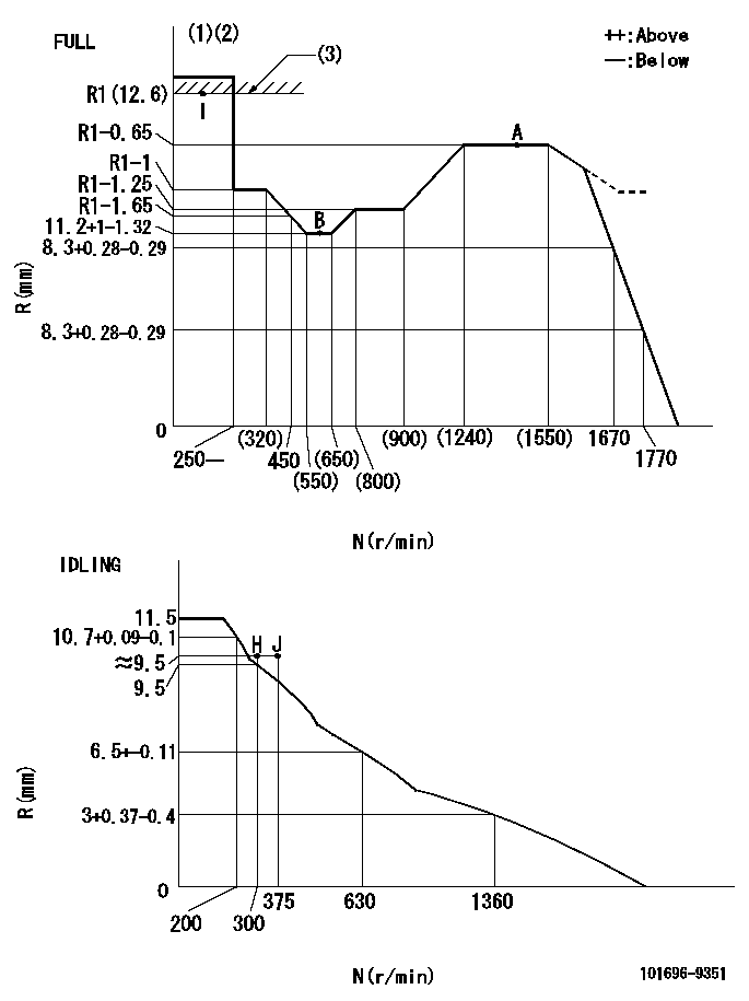
N:Pump speed
R:Rack position (mm)
(1)Torque cam stamping: T1
(2)Tolerance for racks not indicated: +-0.05mm.
(3)RACK LIMIT
----------
T1=J05
----------
----------
T1=J05
----------
Speed control lever angle

F:Full speed
I:Idle
(1)Use the hole at R = aa
(2)Stopper bolt set position 'H'
----------
aa=39mm
----------
a=26.5deg+-5deg b=41deg+-3deg
----------
aa=39mm
----------
a=26.5deg+-5deg b=41deg+-3deg
Stop lever angle
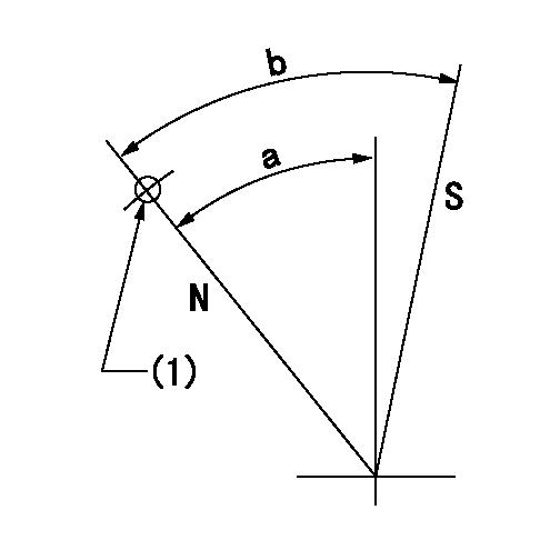
N:Pump normal
S:Stop the pump.
(1)Use the pin at R = aa
----------
aa=28mm
----------
a=37deg+-5deg b=40deg+-5deg
----------
aa=28mm
----------
a=37deg+-5deg b=40deg+-5deg
Timing setting

(1)Pump vertical direction
(2)Position of timer's threaded hole at No 1 cylinder's beginning of injection
(3)-
(4)-
----------
----------
a=(60deg)
----------
----------
a=(60deg)
Information:
Reasonable travel time and mileage will be allowed.
Up to $350 will be allowed for man lift rental to access the injector group.
Product smu/age whichever comes first Caterpillar Dealer Suggested Customer Suggested
Parts % Labor Hrs% Parts % Labor Hrs% Parts % Labor Hrs%
*******Group 2*******
0-500 hrs,
0-12 mo 100.0% 100.0% 0.0% 0.0% 0.0% 0.0%
This is a 2.0-hour job for Group 2
PARTS DISPOSITION
Handle the parts in accordance with your Warranty Bulletin on warranty parts handling.
Rework Procedure
For Group 1 Only:
Step 1: Ensure CEM has cooled prior to beginning work. Use a temp gun to ensure that the temperature of the injector is at a safe to handle temperature.
Image1.1.1
Step 2: Once the CEM is at a safe temperature to begin work, remove air and DEF line connections at the injector. Ensure all permits and appropriate scaffolding or man-lift type equipment with sufficient personnel are on site or available if needed. This procedure may require two individuals with all the required PPE to handle the weight and distance to reach for work to be performed.
Image1.2.1
Step 3: Remove eight bolts and remove injector assembly from the CEM. This step may require two individuals due to the weight of the injector.
Step 4: Remove the nozzle group from the injector.
Image1.4.1
Step 5: Apply Loctite (nickel free) dry film anti-seize on the threads of the 352-0865 nozzle group. Ensure that only the threads receive anti-seize as the nozzle could suffer plugging if anti-seize contaminates the tip. Install the nozzle group with a new gasket onto the injector group and tighten to 9 +/- 2 Nm.
Image1.5.1
Step 6: Reinstall the injector with new nozzle and new gasket into the CEM matching alignment notches and tighten the eight (8) mounting bolts to standard torque. This step may require two individuals due to the weight of the injector.
Image1.6.1
Step 7: Using a stamping die set, the old injector part number must be removed. This can be accomplished using the X stamp and stamping out all of the part numbers (XXXXXXXX) or a grinder can be used to permanently remove the part number.
Step 8: Using the stamping die set, stamp part number 549-2925 on the flange of the injector as shown in image 1.6.1.
Step 9: Install software part number 549-6259 into the dosing cabinet ECM.
Please note that re-commissioning of the SCR system is not required after the software update if the system has already been commissioned.
Have questions with 101696-9351?
Group cross 101696-9351 ZEXEL
Nissan-Diesel
Nissan-Diesel
101696-9351
9 400 616 144
16713Z6364
INJECTION-PUMP ASSEMBLY
FE6B
FE6B