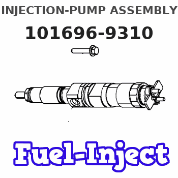
Information injection-pump assembly
BOSCH
9 400 616 141
9400616141
ZEXEL
101696-9310
1016969310
NISSAN-DIESEL
16713Z6371
16713z6371
Rating:
Service parts 101696-9310 INJECTION-PUMP ASSEMBLY:
1.
_
7.
COUPLING PLATE
8.
_
9.
_
11.
Nozzle and Holder
16600-Z5519
12.
Open Pre:MPa(Kqf/cm2)
19.6{200}

15.
NOZZLE SET
Cross reference number
BOSCH
9 400 616 141
9400616141
ZEXEL
101696-9310
1016969310
NISSAN-DIESEL
16713Z6371
16713z6371
Zexel num
Bosch num
Firm num
Name
101696-9310
9 400 616 141
16713Z6371 NISSAN-DIESEL
INJECTION-PUMP ASSEMBLY
FE6T K 14BE INJECTION PUMP ASSY PE6A PE
FE6T K 14BE INJECTION PUMP ASSY PE6A PE
Calibration Data:
Adjustment conditions
Test oil
1404 Test oil ISO4113 or {SAEJ967d}
1404 Test oil ISO4113 or {SAEJ967d}
Test oil temperature
degC
40
40
45
Nozzle and nozzle holder
105780-8140
Bosch type code
EF8511/9A
Nozzle
105780-0000
Bosch type code
DN12SD12T
Nozzle holder
105780-2080
Bosch type code
EF8511/9
Opening pressure
MPa
17.2
Opening pressure
kgf/cm2
175
Injection pipe
Outer diameter - inner diameter - length (mm) mm 6-2-600
Outer diameter - inner diameter - length (mm) mm 6-2-600
Overflow valve
131424-1520
Overflow valve opening pressure
kPa
157
123
191
Overflow valve opening pressure
kgf/cm2
1.6
1.25
1.95
Tester oil delivery pressure
kPa
157
157
157
Tester oil delivery pressure
kgf/cm2
1.6
1.6
1.6
Direction of rotation (viewed from drive side)
Right R
Right R
Injection timing adjustment
Direction of rotation (viewed from drive side)
Right R
Right R
Injection order
1-4-2-6-
3-5
Pre-stroke
mm
3.4
3.35
3.45
Beginning of injection position
Drive side NO.1
Drive side NO.1
Difference between angles 1
Cal 1-4 deg. 60 59.5 60.5
Cal 1-4 deg. 60 59.5 60.5
Difference between angles 2
Cyl.1-2 deg. 120 119.5 120.5
Cyl.1-2 deg. 120 119.5 120.5
Difference between angles 3
Cal 1-6 deg. 180 179.5 180.5
Cal 1-6 deg. 180 179.5 180.5
Difference between angles 4
Cal 1-3 deg. 240 239.5 240.5
Cal 1-3 deg. 240 239.5 240.5
Difference between angles 5
Cal 1-5 deg. 300 299.5 300.5
Cal 1-5 deg. 300 299.5 300.5
Injection quantity adjustment
Adjusting point
-
Rack position
14
Pump speed
r/min
550
550
550
Average injection quantity
mm3/st.
84.8
82.8
86.8
Max. variation between cylinders
%
0
-3.5
3.5
Basic
*
Fixing the rack
*
Standard for adjustment of the maximum variation between cylinders
*
Injection quantity adjustment_02
Adjusting point
-
Rack position
9.7+-0.5
Pump speed
r/min
275
275
275
Average injection quantity
mm3/st.
9.5
7.7
11.3
Max. variation between cylinders
%
0
-10
10
Fixing the rack
*
Standard for adjustment of the maximum variation between cylinders
*
Remarks
Adjust only variation between cylinders; adjust governor according to governor specifications.
Adjust only variation between cylinders; adjust governor according to governor specifications.
Injection quantity adjustment_03
Adjusting point
A
Rack position
R1(14)
Pump speed
r/min
550
550
550
Average injection quantity
mm3/st.
84.8
83.8
85.8
Basic
*
Fixing the lever
*
Boost pressure
kPa
25.3
25.3
Boost pressure
mmHg
190
190
Injection quantity adjustment_04
Adjusting point
B
Rack position
R1-0.1
Pump speed
r/min
850
850
850
Average injection quantity
mm3/st.
91.9
88.7
95.1
Fixing the lever
*
Boost pressure
kPa
25.3
25.3
Boost pressure
mmHg
190
190
Injection quantity adjustment_05
Adjusting point
C
Rack position
R1-0.3
Pump speed
r/min
1400
1400
1400
Average injection quantity
mm3/st.
96.5
93.3
99.7
Fixing the lever
*
Boost pressure
kPa
25.3
25.3
Boost pressure
mmHg
190
190
Injection quantity adjustment_06
Adjusting point
D
Rack position
R2(12.3)
Pump speed
r/min
550
550
550
Average injection quantity
mm3/st.
59.7
58.7
60.7
Fixing the lever
*
Boost pressure
kPa
0
0
0
Boost pressure
mmHg
0
0
0
Injection quantity adjustment_07
Adjusting point
I
Rack position
-
Pump speed
r/min
150
150
150
Average injection quantity
mm3/st.
83.5
83.5
103.5
Fixing the lever
*
Boost pressure
kPa
0
0
0
Boost pressure
mmHg
0
0
0
Rack limit
*
Boost compensator adjustment
Pump speed
r/min
550
550
550
Rack position
R2(12.3)
Boost pressure
kPa
4
2.7
5.3
Boost pressure
mmHg
30
20
40
Boost compensator adjustment_02
Pump speed
r/min
550
550
550
Rack position
R1(14)
Boost pressure
kPa
12
12
12
Boost pressure
mmHg
90
90
90
Timer adjustment
Pump speed
r/min
1170--
Advance angle
deg.
0
0
0
Remarks
Start
Start
Timer adjustment_02
Pump speed
r/min
1120
Advance angle
deg.
0.5
Timer adjustment_03
Pump speed
r/min
1400
Advance angle
deg.
2
1.5
2.5
Remarks
Finish
Finish
Test data Ex:
Governor adjustment
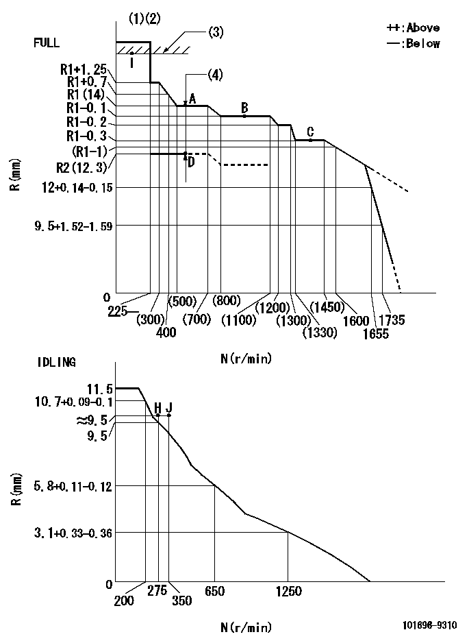
N:Pump speed
R:Rack position (mm)
(1)Torque cam stamping: T1
(2)Tolerance for racks not indicated: +-0.05mm.
(3)RACK LIMIT
(4)Boost compensator stroke: BCL
----------
T1=C44 BCL=(1.7)+-0.1mm
----------
----------
T1=C44 BCL=(1.7)+-0.1mm
----------
Speed control lever angle

F:Full speed
I:Idle
(1)Stopper bolt set position 'H'
----------
----------
a=26.5deg+-5deg b=(44deg)+-3deg
----------
----------
a=26.5deg+-5deg b=(44deg)+-3deg
Stop lever angle

N:Pump normal
S:Stop the pump.
----------
----------
a=20deg+-5deg b=40deg+-5deg
----------
----------
a=20deg+-5deg b=40deg+-5deg
0000001501 ACS

(A) Set screw
(B) Push rod 1
(C) Push rod 2
(D) Cover
1. Aneroid compensator unit adjustment
(1)Select the push rod 2 to obtain L2.
(2)Screw in (A) to obtain L1.
2. Adjustment when mounting the governor.
(1)Set the speed of the pump to N1 r/min and fix the control lever at the full set position.
(2)Screw in the aneroid compensator to obtain the performance shown in the graph above.
(3)As there is hysterisis, measure when the absolute pressure drops.
(4)Hysterisis must not exceed rack position = h1.
----------
N1=1400r/min L1=(1.5)mm L2=11+-0.5mm h1=-
----------
Ra=R3(R1-0.3)mm Rb=(R3-1.7)mm Pa=(92)+-2.7kPa{(690)+-20mmHg} Pb=69.3+-0.7kPa{520+-5mmHg} Q1=(96.5)+-1.6cm3/1000st Q2=77+-3cm3/1000st
----------
N1=1400r/min L1=(1.5)mm L2=11+-0.5mm h1=-
----------
Ra=R3(R1-0.3)mm Rb=(R3-1.7)mm Pa=(92)+-2.7kPa{(690)+-20mmHg} Pb=69.3+-0.7kPa{520+-5mmHg} Q1=(96.5)+-1.6cm3/1000st Q2=77+-3cm3/1000st
Timing setting

(1)Pump vertical direction
(2)Position of timer's threaded hole at No 1 cylinder's beginning of injection
(3)-
(4)-
----------
----------
a=(60deg)
----------
----------
a=(60deg)
Information:
25Oct2017
U-580
A-415
D-489
O-486
Parts stock action only
PRODUCT IMPROVEMENT PROGRAM FOR REMOVING CERTAIN FUEL INJECTORS FROM DEALER STOCK
7750 PI70684
Caterpillar’s obligations under this Service Letter are subject to, and shall not apply in contravention of, the laws, rules, regulations, directives, ordinances, orders, or statutes of the United States, or of any other applicable jurisdiction, without recourse or liability with respect to Caterpillar.
When submitting claim for Parts Stock Action, Use the appropriate 99Z as the s/n, the appropriate Service Letter Program Number as the Part number in the Part Causing Failure field, "7751" as the Group Number, "56" as the Description Code.
The information supplied in this service letter may not be valid after the termination date of this program.Do not perform the work outlined in this Service Letter after the termination date without first contacting your Caterpillar product analyst.
TERMINATION DATE
31Jan2018
PROBLEM
The existing fuel injector can over fuel. If the existing fuel injector fails it can result in engine damage.
ACTION REQUIRED
Remove all injectors with the following part numbers, and within the serial number range from dealer parts stock. Injectors will be packaged between August 9, 2017 and October 13, 2017.
Injectors with a package date prior to August 9, 2017, or after October 13, 2017 do not need to be checked. Date code is below the part number, D##M##Y##, the day is after the D, month is after the M, and Year is the first two numbers after the Y.
Part number and Serial number
457-5312 8C00599034E3 and 8C00599039C0
427-6227 8C005990458F
Remove all injectors with the following part numbers, and within the serial number range from dealer parts stock. Injectors will be packaged between August 9, 2017 and October 13, 2017.
Injectors with a package date prior to August 9, 2017, or after October 13, 2017 do not need to be checked. Date code is below the part number, D##M##Y##, the day is after the D, month is after the M, and Year is the first two numbers after the Y.
Part Number and Serial number
392-0211 2066755 through 2068587, inclusive
392-0205 2066755 through 2068587, inclusive
392-0219 2066755 through 2068587, inclusive
392-0217 2066755 through 2068587, inclusive
392-0202 2066755 through 2068587, inclusive
392-0223 2066755 through 2068587, inclusive
392-0216 2066755 through 2068587, inclusive
392-0221 2066755 through 2068587, inclusive
392-0225 2066755 through 2068587, inclusive
392-0214 2066755 through 2068587, inclusive
392-0206 2066755 through 2068587, inclusive
Remove all injectors with the following part numbers, and within the serial number range from dealer parts stock. Injectors will be packaged between August 9, 2017 and October 20, 2017.
Injectors with a package date prior to August 9, 2017, or after October 20, 2017 do not need to be checked. Date code is below the part number, D##M##Y##, the day is after the D, month is after the M, and Year is the first two numbers after the Y.
Part Number and Serial number
111-3718 865395 through 868934, inclusive
4P-9075 865395 through 868934, inclusive
4P-9076 865395
Have questions with 101696-9310?
Group cross 101696-9310 ZEXEL
Nissan-Diesel
101696-9310
9 400 616 141
16713Z6371
INJECTION-PUMP ASSEMBLY
FE6T
FE6T