Information injection-pump assembly
BOSCH
9 400 616 140
9400616140
ZEXEL
101696-9300
1016969300
NISSAN-DIESEL
16713Z6370
16713z6370

Rating:
Service parts 101696-9300 INJECTION-PUMP ASSEMBLY:
1.
_
7.
COUPLING PLATE
8.
_
9.
_
11.
Nozzle and Holder
16600-Z5570
12.
Open Pre:MPa(Kqf/cm2)
21.6{220}
15.
NOZZLE SET
Cross reference number
BOSCH
9 400 616 140
9400616140
ZEXEL
101696-9300
1016969300
NISSAN-DIESEL
16713Z6370
16713z6370
Zexel num
Bosch num
Firm num
Name
101696-9300
9 400 616 140
16713Z6370 NISSAN-DIESEL
INJECTION-PUMP ASSEMBLY
FE6T * K
FE6T * K
Calibration Data:
Adjustment conditions
Test oil
1404 Test oil ISO4113 or {SAEJ967d}
1404 Test oil ISO4113 or {SAEJ967d}
Test oil temperature
degC
40
40
45
Nozzle and nozzle holder
105780-8140
Bosch type code
EF8511/9A
Nozzle
105780-0000
Bosch type code
DN12SD12T
Nozzle holder
105780-2080
Bosch type code
EF8511/9
Opening pressure
MPa
17.2
Opening pressure
kgf/cm2
175
Injection pipe
Outer diameter - inner diameter - length (mm) mm 6-2-600
Outer diameter - inner diameter - length (mm) mm 6-2-600
Overflow valve
131424-1520
Overflow valve opening pressure
kPa
157
123
191
Overflow valve opening pressure
kgf/cm2
1.6
1.25
1.95
Tester oil delivery pressure
kPa
157
157
157
Tester oil delivery pressure
kgf/cm2
1.6
1.6
1.6
Direction of rotation (viewed from drive side)
Right R
Right R
Injection timing adjustment
Direction of rotation (viewed from drive side)
Right R
Right R
Injection order
1-4-2-6-
3-5
Pre-stroke
mm
3.4
3.35
3.45
Beginning of injection position
Drive side NO.1
Drive side NO.1
Difference between angles 1
Cal 1-4 deg. 60 59.5 60.5
Cal 1-4 deg. 60 59.5 60.5
Difference between angles 2
Cyl.1-2 deg. 120 119.5 120.5
Cyl.1-2 deg. 120 119.5 120.5
Difference between angles 3
Cal 1-6 deg. 180 179.5 180.5
Cal 1-6 deg. 180 179.5 180.5
Difference between angles 4
Cal 1-3 deg. 240 239.5 240.5
Cal 1-3 deg. 240 239.5 240.5
Difference between angles 5
Cal 1-5 deg. 300 299.5 300.5
Cal 1-5 deg. 300 299.5 300.5
Injection quantity adjustment
Adjusting point
-
Rack position
12.5
Pump speed
r/min
1500
1500
1500
Average injection quantity
mm3/st.
83.7
82.1
85.3
Max. variation between cylinders
%
0
-3.5
3.5
Basic
*
Fixing the rack
*
Standard for adjustment of the maximum variation between cylinders
*
Injection quantity adjustment_02
Adjusting point
H
Rack position
9.5+-0.5
Pump speed
r/min
300
300
300
Average injection quantity
mm3/st.
9.5
7.7
11.3
Max. variation between cylinders
%
0
-10
10
Fixing the rack
*
Standard for adjustment of the maximum variation between cylinders
*
Injection quantity adjustment_03
Adjusting point
A
Rack position
R1(12.5)
Pump speed
r/min
1500
1500
1500
Average injection quantity
mm3/st.
83.7
82.7
84.7
Basic
*
Fixing the lever
*
Injection quantity adjustment_04
Adjusting point
B
Rack position
R1-0.55
Pump speed
r/min
900
900
900
Average injection quantity
mm3/st.
68.7
66.7
70.7
Fixing the lever
*
Injection quantity adjustment_05
Adjusting point
I
Rack position
-
Pump speed
r/min
150
150
150
Average injection quantity
mm3/st.
85
85
105
Fixing the lever
*
Rack limit
*
Timer adjustment
Pump speed
r/min
1050--
Advance angle
deg.
0
0
0
Remarks
Start
Start
Timer adjustment_02
Pump speed
r/min
1000
Advance angle
deg.
0.5
Timer adjustment_03
Pump speed
r/min
1500
Advance angle
deg.
2
1.5
2.5
Remarks
Finish
Finish
Test data Ex:
Governor adjustment
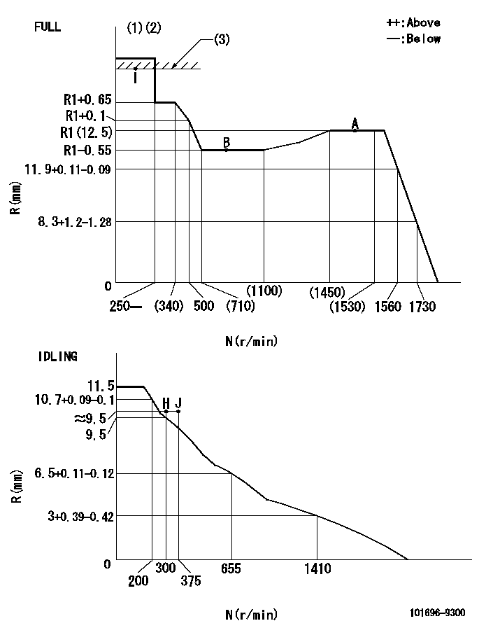
N:Pump speed
R:Rack position (mm)
(1)Torque cam stamping: T1
(2)Tolerance for racks not indicated: +-0.05mm.
(3)RACK LIMIT
----------
T1=C35
----------
----------
T1=C35
----------
Speed control lever angle

F:Full speed
I:Idle
(1)Use the hole at R = aa
(2)Stopper bolt set position 'H'
----------
aa=100mm
----------
a=26.5deg+-5deg b=(37deg)+-3deg
----------
aa=100mm
----------
a=26.5deg+-5deg b=(37deg)+-3deg
Stop lever angle

N:Pump normal
S:Stop the pump.
----------
----------
a=20deg+-5deg b=40deg+-5deg
----------
----------
a=20deg+-5deg b=40deg+-5deg
Timing setting

(1)Pump vertical direction
(2)Position of timer's threaded hole at No 1 cylinder's beginning of injection
(3)-
(4)-
----------
----------
a=(60deg)
----------
----------
a=(60deg)
Information:
AFFECTED PRODUCT
Model Identification Number
C175-20 R4F00100-00120
PARTS NEEDED
Qty
Part Number Description
20 2153198 SEAL-FUEL SYSTEM
20 3618205 SEAL-FUEL SYSTEM
20 3618206 SEAL-FUEL SYSTEM
20 3618207 SEAL-FUEL SYSTEM
20 5272962 CLAMP-INJECTOR
In order to allow equitable parts availability to all participating dealers, please limit your initial parts order to not exceed 32% of dealership population. This is an initial order recommendation only, and the ultimate responsibility for ordering the total number of parts needed to satisfy the program lies with the dealer.
ACTION REQUIRED
Replace the injector hold down clamps in accordance with Disassembly and Assembly, M0067480, "Electronic Unit Injector - Remove" and "Electronic Unit Injector - Install".
Rework the rear heat shields per the attached Rework Procedure.
SERVICE CLAIM ALLOWANCES
Product smu/age whichever comes first Caterpillar Dealer Suggested Customer Suggested
Parts % Labor Hrs% Parts % Labor Hrs% Parts % Labor Hrs%
0-6000 hrs,
0-12 mo 100.0% 100.0% 0.0% 0.0% 0.0% 0.0%
This is a 12.0-hour job
PARTS DISPOSITION
Handle the parts in accordance with your Warranty Bulletin on warranty parts handling.
Rework Procedure
1. Remove the rear 461-6090 and 461-6080 Heat Shields.
Image1.1.1
2. Inspect the inside of the shield for contact with the exhaust log bellows.
Image1.2.1
3. If witness marks are found compress the shield 2 mm at that location using a mallet. Ensure a block of wood is behind the shield when compressing. This operation should be completed with multiple light strikes.
Image1.3.1
4. Reassemble heat shield in reverse order of removal.
Have questions with 101696-9300?
Group cross 101696-9300 ZEXEL
Nissan-Diesel
101696-9300
9 400 616 140
16713Z6370
INJECTION-PUMP ASSEMBLY
FE6T
FE6T