Information injection-pump assembly
BOSCH
9 400 616 136
9400616136
ZEXEL
101696-9090
1016969090
NISSAN-DIESEL
1671395210
1671395210
Rating:
Service parts 101696-9090 INJECTION-PUMP ASSEMBLY:
1.
_

7.
COUPLING PLATE
8.
_
9.
_
11.
Nozzle and Holder
1660095015
12.
Open Pre:MPa(Kqf/cm2)
19.6(200)
15.
NOZZLE SET
Cross reference number
BOSCH
9 400 616 136
9400616136
ZEXEL
101696-9090
1016969090
NISSAN-DIESEL
1671395210
1671395210
Zexel num
Bosch num
Firm num
Name
101696-9090
9 400 616 136
1671395210 NISSAN-DIESEL
INJECTION-PUMP ASSEMBLY
NE6T * K 14BF INJECTION PUMP ASSY PE6AD PE
NE6T * K 14BF INJECTION PUMP ASSY PE6AD PE
Calibration Data:
Adjustment conditions
Test oil
1404 Test oil ISO4113 or {SAEJ967d}
1404 Test oil ISO4113 or {SAEJ967d}
Test oil temperature
degC
40
40
45
Nozzle and nozzle holder
105780-8140
Bosch type code
EF8511/9A
Nozzle
105780-0000
Bosch type code
DN12SD12T
Nozzle holder
105780-2080
Bosch type code
EF8511/9
Opening pressure
MPa
17.2
Opening pressure
kgf/cm2
175
Injection pipe
Outer diameter - inner diameter - length (mm) mm 6-2-600
Outer diameter - inner diameter - length (mm) mm 6-2-600
Overflow valve
131424-1520
Overflow valve opening pressure
kPa
157
123
191
Overflow valve opening pressure
kgf/cm2
1.6
1.25
1.95
Tester oil delivery pressure
kPa
157
157
157
Tester oil delivery pressure
kgf/cm2
1.6
1.6
1.6
Direction of rotation (viewed from drive side)
Right R
Right R
Injection timing adjustment
Direction of rotation (viewed from drive side)
Right R
Right R
Injection order
1-4-2-6-
3-5
Pre-stroke
mm
3.7
3.65
3.75
Beginning of injection position
Drive side NO.1
Drive side NO.1
Difference between angles 1
Cal 1-4 deg. 60 59.5 60.5
Cal 1-4 deg. 60 59.5 60.5
Difference between angles 2
Cyl.1-2 deg. 120 119.5 120.5
Cyl.1-2 deg. 120 119.5 120.5
Difference between angles 3
Cal 1-6 deg. 180 179.5 180.5
Cal 1-6 deg. 180 179.5 180.5
Difference between angles 4
Cal 1-3 deg. 240 239.5 240.5
Cal 1-3 deg. 240 239.5 240.5
Difference between angles 5
Cal 1-5 deg. 300 299.5 300.5
Cal 1-5 deg. 300 299.5 300.5
Injection quantity adjustment
Adjusting point
-
Rack position
12.6
Pump speed
r/min
1400
1400
1400
Average injection quantity
mm3/st.
95.5
93.9
97.1
Max. variation between cylinders
%
0
-3.5
3.5
Basic
*
Fixing the rack
*
Standard for adjustment of the maximum variation between cylinders
*
Injection quantity adjustment_02
Adjusting point
H
Rack position
9.5+-0.5
Pump speed
r/min
275
275
275
Average injection quantity
mm3/st.
8
6.2
9.8
Max. variation between cylinders
%
0
-10
10
Fixing the rack
*
Standard for adjustment of the maximum variation between cylinders
*
Injection quantity adjustment_03
Adjusting point
A
Rack position
R1(12.6)
Pump speed
r/min
1400
1400
1400
Average injection quantity
mm3/st.
95.5
94.5
96.5
Basic
*
Fixing the lever
*
Injection quantity adjustment_04
Adjusting point
B
Rack position
R1-0.1
Pump speed
r/min
900
900
900
Average injection quantity
mm3/st.
85
81.8
88.2
Fixing the lever
*
Injection quantity adjustment_05
Adjusting point
C
Rack position
R1+0.1
Pump speed
r/min
400
400
400
Average injection quantity
mm3/st.
66.5
63.3
69.7
Fixing the lever
*
Injection quantity adjustment_06
Adjusting point
I
Rack position
-
Pump speed
r/min
150
150
150
Average injection quantity
mm3/st.
85
85
105
Fixing the lever
*
Rack limit
*
Timer adjustment
Pump speed
r/min
920--
Advance angle
deg.
0
0
0
Remarks
Start
Start
Timer adjustment_02
Pump speed
r/min
870
Advance angle
deg.
0.5
Timer adjustment_03
Pump speed
r/min
1400
Advance angle
deg.
2
1.5
2.5
Remarks
Finish
Finish
Test data Ex:
Governor adjustment
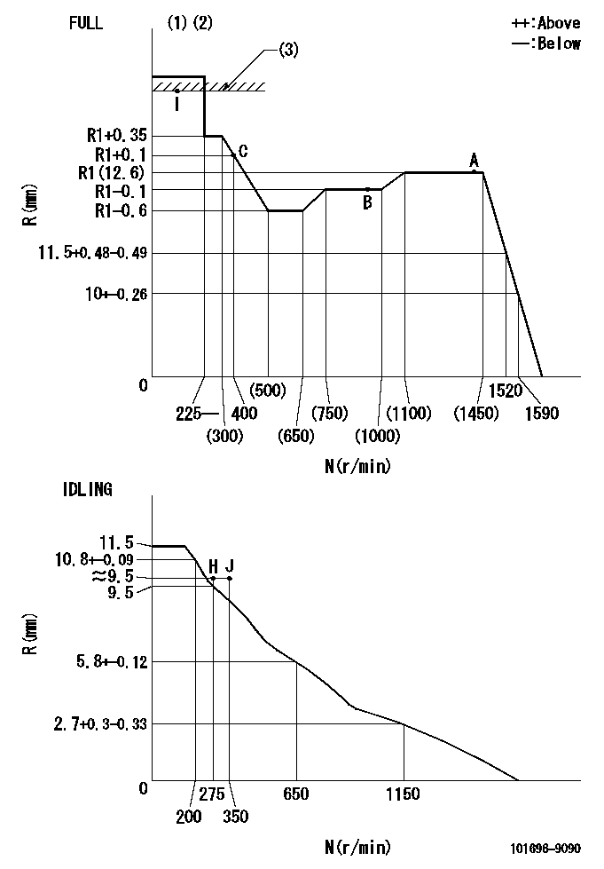
N:Pump speed
R:Rack position (mm)
(1)Torque cam stamping: T1
(2)Tolerance for racks not indicated: +-0.05mm.
(3)RACK LIMIT
----------
T1=M64
----------
----------
T1=M64
----------
Speed control lever angle

F:Full speed
I:Idle
(1)Stopper bolt set position 'H'
----------
----------
a=26.5deg+-5deg b=(43deg)+-3deg
----------
----------
a=26.5deg+-5deg b=(43deg)+-3deg
Stop lever angle
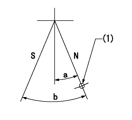
N:Pump normal
S:Stop the pump.
(1)Use the hole at R = aa
----------
aa=36mm
----------
a=20deg+-5deg b=40deg+-5deg
----------
aa=36mm
----------
a=20deg+-5deg b=40deg+-5deg
Timing setting

(1)Pump vertical direction
(2)Coupling's key groove position at No 1 cylinder's beginning of injection
(3)-
(4)-
----------
----------
a=(40deg)
----------
----------
a=(40deg)
Information:
Temporary corrections to the charts in this book will be printed in the publication ENGINE NEWS. Announcement for revised reprints of this book will be made in PREVIEW.These instructions are intended to acquaint you with the content of the rack setting charts. A description is given of the information to be found under each column heading. Read these instructions carefully so you can better understand the information presented.After reading and understanding these instructions, use the following suggestions to aid in the actual use of the rack setting charts.1. Determine and write down the engine model and engine serial number.2. Locate the correct rack setting chart.3. Locate the correct segment of the chart being used. Particular attention must be focused on the model and serial number.4. Read all notes pertaining to the engine being repaired. The notes are just as important as any other information that is presented on the rack setting chart.Column Headings
Column headings and arrangement of material can vary from chart to chart according to data requirements for the engines. A brief description of each column heading, note and symbol follows. See Fig. 1.Model
The MODEL column lists the description of the engine, and the serial number range to which the data applies. Be sure to use the data from the correct serial number range for the engine being repaired.Engine Full Load RPM
The column lists the engine speed (under load) at which the rack is positioned to permit maximum allowable amount of fuel to the engine per unit of time. Turbocharger speed, inlet manifold pressure and horsepower output are at their maximum for the listed rack setting. A tolerance of 10 RPM is allowed.Engine High Idle RPM
This column lists the high idle speed of the bare engine when driving a dynamometer. Use the figures in the chart when adjusting high idle in the truck. A tolerance of 30 RPM is allowed in most applications.Brake Horsepower
This column lists the power available at the flywheel, without fan, and within the limitations indicated in the charts. A tolerance of 3% of this value is normal from a new or reconditioned engine.
Fig. 1Rack Setting
The rack setting is the distance the rack must travel from the centered (sometimes referred to as zero) position, to supply sufficient fuel, to produce the expected power output of the engine. Rack setting is controlled by a stop bar or torque spring that is located within the governor. The stop bar and/or torque spring limits the maximum travel of the fuel rack. Rack setting procedure is explained and illustrated in the TESTING AND ADJUSTING Section of the applicable service manual.All rack settings are plus (+) settings unless otherwise indicated with a minus (-) sign. See Fig. 2.Torque Spring And Spacer
This column lists the part number and thickness of the torque spring, and only those spacers or shims installed between the torque spring and stop. Any shims located behind the stop are not listed. The dimensions are in inches and are for means of identification.
Fig.
Have questions with 101696-9090?
Group cross 101696-9090 ZEXEL
Nissan-Diesel
Nissan-Diesel
101696-9090
9 400 616 136
1671395210
INJECTION-PUMP ASSEMBLY
NE6T
NE6T