Information injection-pump assembly
BOSCH
9 400 619 801
9400619801
ZEXEL
101695-3840
1016953840
Rating:
Service parts 101695-3840 INJECTION-PUMP ASSEMBLY:
1.
_
5.
AUTOM. ADVANCE MECHANIS
6.
COUPLING PLATE
7.
COUPLING PLATE
8.
_
9.
_
11.
Nozzle and Holder
12.
Open Pre:MPa(Kqf/cm2)
19.6(200)

15.
NOZZLE SET
Cross reference number
BOSCH
9 400 619 801
9400619801
ZEXEL
101695-3840
1016953840
Zexel num
Bosch num
Firm num
Name
Calibration Data:
Adjustment conditions
Test oil
1404 Test oil ISO4113 or {SAEJ967d}
1404 Test oil ISO4113 or {SAEJ967d}
Test oil temperature
degC
40
40
45
Nozzle and nozzle holder
105780-8140
Bosch type code
EF8511/9A
Nozzle
105780-0000
Bosch type code
DN12SD12T
Nozzle holder
105780-2080
Bosch type code
EF8511/9
Opening pressure
MPa
17.2
Opening pressure
kgf/cm2
175
Injection pipe
Outer diameter - inner diameter - length (mm) mm 6-2-600
Outer diameter - inner diameter - length (mm) mm 6-2-600
Tester oil delivery pressure
kPa
157
157
157
Tester oil delivery pressure
kgf/cm2
1.6
1.6
1.6
Direction of rotation (viewed from drive side)
Right R
Right R
Injection timing adjustment
Direction of rotation (viewed from drive side)
Right R
Right R
Injection order
1-5-3-6-
2-4
Pre-stroke
mm
3.6
3.55
3.65
Beginning of injection position
Drive side NO.1
Drive side NO.1
Difference between angles 1
Cal 1-5 deg. 60 59.5 60.5
Cal 1-5 deg. 60 59.5 60.5
Difference between angles 2
Cal 1-3 deg. 120 119.5 120.5
Cal 1-3 deg. 120 119.5 120.5
Difference between angles 3
Cal 1-6 deg. 180 179.5 180.5
Cal 1-6 deg. 180 179.5 180.5
Difference between angles 4
Cyl.1-2 deg. 240 239.5 240.5
Cyl.1-2 deg. 240 239.5 240.5
Difference between angles 5
Cal 1-4 deg. 300 299.5 300.5
Cal 1-4 deg. 300 299.5 300.5
Injection quantity adjustment
Adjusting point
A
Rack position
9.7
Pump speed
r/min
1000
1000
1000
Average injection quantity
mm3/st.
37.6
36.6
38.6
Max. variation between cylinders
%
0
-2.5
2.5
Basic
*
Fixing the lever
*
Injection quantity adjustment_02
Adjusting point
-
Rack position
8.9+-0.5
Pump speed
r/min
425
425
425
Average injection quantity
mm3/st.
8
7
9
Max. variation between cylinders
%
0
-15
15
Fixing the rack
*
Remarks
Adjust only variation between cylinders; adjust governor according to governor specifications.
Adjust only variation between cylinders; adjust governor according to governor specifications.
Test data Ex:
Governor adjustment
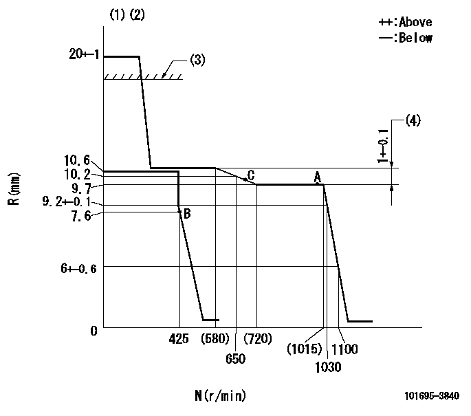
N:Pump speed
R:Rack position (mm)
(1)Target notch: K
(2)Tolerance for racks not indicated: +-0.05mm.
(3)RACK CAP: R1
(4)Rack difference between N = N1 and N = N2
----------
K=18 R1=(17.5)mm N1=1000r/min N2=450r/min
----------
----------
K=18 R1=(17.5)mm N1=1000r/min N2=450r/min
----------
Speed control lever angle
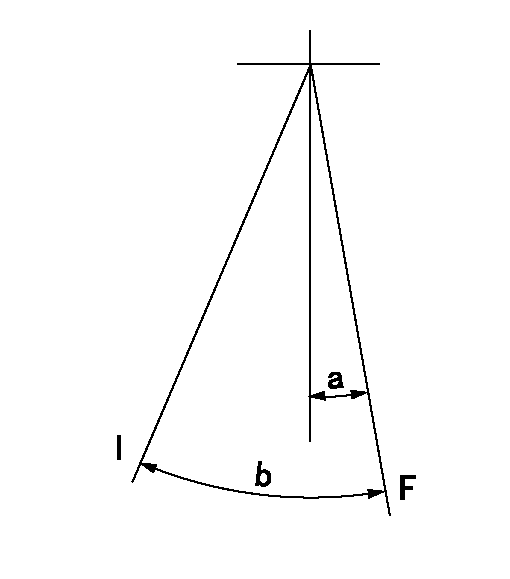
F:Full speed
I:Idle
----------
----------
a=18deg+-5deg b=29deg+-5deg
----------
----------
a=18deg+-5deg b=29deg+-5deg
Stop lever angle

N:Pump normal
S:Stop the pump.
(1)At delivery
----------
----------
a=26.5deg+-5deg b=53deg+-5deg
----------
----------
a=26.5deg+-5deg b=53deg+-5deg
Timing setting

(1)Pump vertical direction
(2)Position of key groove at No 1 cylinder's beginning of injection
(3)Stamp aligning marks on the pump housing flange.
(4)-
----------
----------
a=59deg36min+-3deg b=0deg24min+-30min
----------
----------
a=59deg36min+-3deg b=0deg24min+-30min
Information:
(1) Torque for bolt that holds the impeller ... 39 3 N m (28 2 lb ft)(2) Shaft diameter at carbon seal assembly seat area must be ... 19.10 0.05 mm (.752 .002 in) Use 4C9500 Quick Cure Primer to clean the water pump shaft and the ceramic ring seal counterbore in the pump housing.(3) Ring and water seal. Use a 125-9622 Seal Installation Tool and hand pressure to install the rubber seal and ceramic ring as a unit in the pump housing bore. Make sure the identification mark (holes or groove) on the ceramic ring face is installed inside the rubber seal.(4) Seal assembly. a. Remove the spring from the seal.b. Put clean water on the seal assembly as the only lubrication for assembly. Do not get any grease or oil on the seal faces.c. Do not stretch the rubber of the seal assembly at installation. If the seal is stretched, the service life is shortened.d. Use a 125-9622 Seal Installation Tool and hand pressure to install the seal assembly on the pump shaft until the carbon face makes light contact with the smooth face of the ceramic ring. The carbon seal assembly must rotate with the water pump shaft. Do not use any lubricant (except clean water) that will reduce the friction between the seal and the shaft.e. Install the carbon seal assembly spring.(5) Oil seal. Put a small amount of clean engine oil on the lip of the seal at assembly. Install it with the lip toward the bearings as shown.(6) Torque for bolt that holds the gear ... 215 40 N m (160 30 lb ft)Water Pump (135-4925 and 135-4926)
(1) With flat side towards housing install oil seal flush with housing using a suitable driver. DO NOT lubricate lip of seal.(2) Install Shaft. Shaft diameter at unitized seal assembly must be ... 19.10 .01 mm (.752 .0004 in). Using a 138-9299 Installation Tool over the shaft with the chamfer facing out, carefully insert the shaft into the oil seal. Position the shaft to center the oil seal lips on the shaft running surface. Then remove installation tool from shaft.(3) Install bearings. Slide the bearing assembly over the shaft and into the housing. Torque the bearing retainer plate bolts to ... 25 6 N m (19 4 lb ft)(4) Torque for gear retaining bolt ... 215 40 N m (158 30 lb ft)(5) Unitized seal. Using a 139-0088 Installation Tool and a suitable press to install the seal onto the pump shaft and into the housing bore, insure that the seal is fully seated in the housing bore. DO NOT use a hammer to install the seal as damage to ceramic sealing face will occur.(6) Bolt torque for the impeller retaining bolts is ... 39 3 N m (28 2 lb ft)
(1) With flat side towards housing install oil seal flush with housing using a suitable driver. DO NOT lubricate lip of seal.(2) Install Shaft. Shaft diameter at unitized seal assembly must be ... 19.10 .01 mm (.752 .0004 in). Using a 138-9299 Installation Tool over the shaft with the chamfer facing out, carefully insert the shaft into the oil seal. Position the shaft to center the oil seal lips on the shaft running surface. Then remove installation tool from shaft.(3) Install bearings. Slide the bearing assembly over the shaft and into the housing. Torque the bearing retainer plate bolts to ... 25 6 N m (19 4 lb ft)(4) Torque for gear retaining bolt ... 215 40 N m (158 30 lb ft)(5) Unitized seal. Using a 139-0088 Installation Tool and a suitable press to install the seal onto the pump shaft and into the housing bore, insure that the seal is fully seated in the housing bore. DO NOT use a hammer to install the seal as damage to ceramic sealing face will occur.(6) Bolt torque for the impeller retaining bolts is ... 39 3 N m (28 2 lb ft)