Information injection-pump assembly
BOSCH
9 400 616 131
9400616131
ZEXEL
101695-3811
1016953811
KOMATSU
6207711520
6207711520
Rating:
Service parts 101695-3811 INJECTION-PUMP ASSEMBLY:
1.
_
5.
AUTOM. ADVANCE MECHANIS
6.
COUPLING PLATE
7.
COUPLING PLATE
8.
_
9.
_
11.
Nozzle and Holder
6207-11-3600
12.
Open Pre:MPa(Kqf/cm2)
19.6{200}

15.
NOZZLE SET
Cross reference number
BOSCH
9 400 616 131
9400616131
ZEXEL
101695-3811
1016953811
KOMATSU
6207711520
6207711520
Zexel num
Bosch num
Firm num
Name
101695-3811
9 400 616 131
6207711520 KOMATSU
INJECTION-PUMP ASSEMBLY
S6D95L K 14BE INJECTION PUMP ASSY PE6A PE
S6D95L K 14BE INJECTION PUMP ASSY PE6A PE
Calibration Data:
Adjustment conditions
Test oil
1404 Test oil ISO4113 or {SAEJ967d}
1404 Test oil ISO4113 or {SAEJ967d}
Test oil temperature
degC
40
40
45
Nozzle and nozzle holder
105780-8140
Bosch type code
EF8511/9A
Nozzle
105780-0000
Bosch type code
DN12SD12T
Nozzle holder
105780-2080
Bosch type code
EF8511/9
Opening pressure
MPa
17.2
Opening pressure
kgf/cm2
175
Injection pipe
Outer diameter - inner diameter - length (mm) mm 6-2-600
Outer diameter - inner diameter - length (mm) mm 6-2-600
Tester oil delivery pressure
kPa
157
157
157
Tester oil delivery pressure
kgf/cm2
1.6
1.6
1.6
Direction of rotation (viewed from drive side)
Right R
Right R
Injection timing adjustment
Direction of rotation (viewed from drive side)
Right R
Right R
Injection order
1-5-3-6-
2-4
Pre-stroke
mm
3.6
3.55
3.65
Beginning of injection position
Drive side NO.1
Drive side NO.1
Difference between angles 1
Cal 1-5 deg. 60 59.5 60.5
Cal 1-5 deg. 60 59.5 60.5
Difference between angles 2
Cal 1-3 deg. 120 119.5 120.5
Cal 1-3 deg. 120 119.5 120.5
Difference between angles 3
Cal 1-6 deg. 180 179.5 180.5
Cal 1-6 deg. 180 179.5 180.5
Difference between angles 4
Cyl.1-2 deg. 240 239.5 240.5
Cyl.1-2 deg. 240 239.5 240.5
Difference between angles 5
Cal 1-4 deg. 300 299.5 300.5
Cal 1-4 deg. 300 299.5 300.5
Injection quantity adjustment
Adjusting point
A
Rack position
12
Pump speed
r/min
1200
1200
1200
Average injection quantity
mm3/st.
65
64
66
Max. variation between cylinders
%
0
-2.5
2.5
Basic
*
Fixing the lever
*
Boost pressure
kPa
36
36
Boost pressure
mmHg
270
270
Injection quantity adjustment_02
Adjusting point
-
Rack position
10.4+-0.
5
Pump speed
r/min
385
385
385
Average injection quantity
mm3/st.
12.5
11.5
13.5
Max. variation between cylinders
%
0
-15
15
Fixing the rack
*
Boost pressure
kPa
0
0
0
Boost pressure
mmHg
0
0
0
Remarks
Adjust only variation between cylinders; adjust governor according to governor specifications.
Adjust only variation between cylinders; adjust governor according to governor specifications.
Boost compensator adjustment
Pump speed
r/min
550
550
550
Rack position
11.1
Boost pressure
kPa
6.7
4
9.4
Boost pressure
mmHg
50
30
70
Boost compensator adjustment_02
Pump speed
r/min
550
550
550
Rack position
12.3
Boost pressure
kPa
22.7
16
29.4
Boost pressure
mmHg
170
120
220
Test data Ex:
Governor adjustment
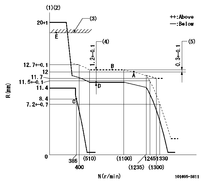
N:Pump speed
R:Rack position (mm)
(1)Target notch: K
(2)Tolerance for racks not indicated: +-0.05mm.
(3)RACK LIMIT: RAL
(4)Boost compensator stroke
(5)Rack difference between N = N1 and N = N2
----------
K=9 RAL=15+0.2mm N1=1200r/min N2=800r/min
----------
----------
K=9 RAL=15+0.2mm N1=1200r/min N2=800r/min
----------
Speed control lever angle
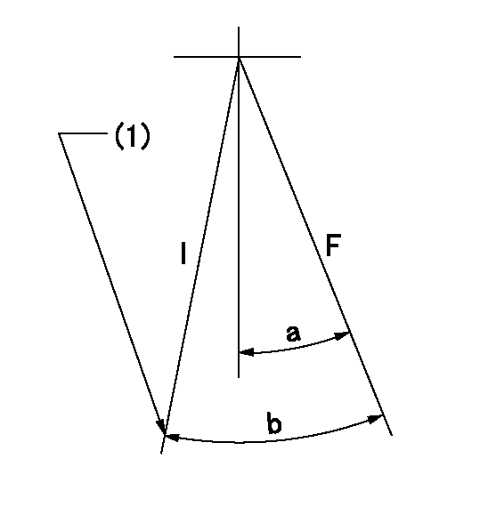
F:Full speed
I:Idle
(1)Stopper bolt setting
----------
----------
a=12deg+-5deg b=27deg+-5deg
----------
----------
a=12deg+-5deg b=27deg+-5deg
Stop lever angle

N:Pump normal
S:Stop the pump.
(1)Pump speed aa and rack position bb (to be sealed at delivery)
----------
aa=0r/min bb=1-0.2mm
----------
a=21deg+-5deg b=(55deg)
----------
aa=0r/min bb=1-0.2mm
----------
a=21deg+-5deg b=(55deg)
Timing setting

(1)Pump vertical direction
(2)Position of key groove at No 1 cylinder's beginning of injection
(3)Stamp aligning marks on the pump housing flange.
(4)-
----------
----------
a=59deg36min+-3deg b=0deg24min+-30min
----------
----------
a=59deg36min+-3deg b=0deg24min+-30min
Information:
Guidelines For Reusable Parts; Valves And Valve Springs, SEBF8002 and SEBF8034 have the procedure and specifications necessary for checking used valves and valve springs.(1) 4W2471 Spring for valves (outer) (new): Length under test force ... 53.24 mm (2.096 in)Test force ... 245 24 N (55 5 lb)Use again minimum load at length under test force ... 211 N (48 lb)Length of spring at valve open position ... 39.0 mm (1.54 in)Use again minimum load at valve open position ... 755 N (170 lb)Free length after test ... 59.5 mm (2.34 in)Outside diameter ... 37.31 mm (1.469 in)Spring must not be bent more than ... 2.10 mm (.083 in)(1) 4W2472 Spring for valves (inner) (new): Length under test force ... 50.24 mm (1.978 in)Test force ... 178 18 N (40 4 lb)Use again minimum load at length under test force ... 155 N (35 lb)Length of spring at valve open position ... 36.0 mm (1.42 in)Use again minimum load at valve open position ... 321 N (72 lb)Free length after test ... 65.7 mm (2.60 in)Outside diameter ... 25.13 mm (.989 in)Spring must not be bent more than ... 2.30 mm (.091 in)(2) Height to top of valve guide ... 27.2 .8 mm (1.07 .03 in)(3) Diameter of valve stem (new) ... 9.441 .01 mm (.3717 .0004 in)Use again minimum diameter of valve stems:Exhaust ... 9.408 mm (.3704 in)Inlet ... 9.408 mm (.3704 in)Bore in valve guide with guide installed in the head (new) ... 9.487 0.025 mm (.3735 .0010 in)Use again dimension for valve guide bore ... 9.538 mm (.3755 in)(4) Diameter of valve head: Exhaust valve ... 41.81 0.13 mm (1.646 .005 in)Inlet valve ... 44.98 0.13 mm (1.771 .005 in)(5) Angle of inlet valve face ... 29 1/4 1/4 degreesAngle of exhaust valve face ... 44 1/4 1/4 degrees (6) Depth of bore in head for valve seat insert ... 13.01 0.35 mm (.512 .014 in)(7) Diameter of valve seat insert for inlet valve ... 46.025 0.013 mm (1.8120 .0005 in) Bore in head for valve seat insert for inlet valve ... 45.949 0.025 mm (1.8090 .0010 in)Diameter of valve seat insert for exhaust valve ... 42.850 0.013 mm (1.6870 .0005 in)Bore in head for valve seat insert for exhaust valve ... 42.774 0.025 mm (1.6840 .0010 in)(8) Angle of face of inlet valve seat insert ... 30 1/4 1/2 degreesAngle of face of exhaust valve seat insert ... 44 3/4 1/2 degrees(9) Dimension from end of closed valve to machined face of head. Maximum permissible dimension:Below (recessed from) machined face ... 1.22 mm (.048 in)Above (extended from) machined face ... 0.20
Have questions with 101695-3811?
Group cross 101695-3811 ZEXEL
Komatsu
Komatsu
101695-3811
9 400 616 131
6207711520
INJECTION-PUMP ASSEMBLY
S6D95L
S6D95L