Information injection-pump assembly
ZEXEL
101695-3810
1016953810

Rating:
Cross reference number
ZEXEL
101695-3810
1016953810
Zexel num
Bosch num
Firm num
Name
101695-3810
INJECTION-PUMP ASSEMBLY
Calibration Data:
Adjustment conditions
Test oil
1404 Test oil ISO4113 or {SAEJ967d}
1404 Test oil ISO4113 or {SAEJ967d}
Test oil temperature
degC
40
40
45
Nozzle and nozzle holder
105780-8140
Bosch type code
EF8511/9A
Nozzle
105780-0000
Bosch type code
DN12SD12T
Nozzle holder
105780-2080
Bosch type code
EF8511/9
Opening pressure
MPa
17.2
Opening pressure
kgf/cm2
175
Injection pipe
Outer diameter - inner diameter - length (mm) mm 6-2-600
Outer diameter - inner diameter - length (mm) mm 6-2-600
Tester oil delivery pressure
kPa
157
157
157
Tester oil delivery pressure
kgf/cm2
1.6
1.6
1.6
Direction of rotation (viewed from drive side)
Right R
Right R
Injection timing adjustment
Direction of rotation (viewed from drive side)
Right R
Right R
Injection order
1-5-3-6-
2-4
Pre-stroke
mm
3.6
3.55
3.65
Beginning of injection position
Drive side NO.1
Drive side NO.1
Difference between angles 1
Cal 1-5 deg. 60 59.5 60.5
Cal 1-5 deg. 60 59.5 60.5
Difference between angles 2
Cal 1-3 deg. 120 119.5 120.5
Cal 1-3 deg. 120 119.5 120.5
Difference between angles 3
Cal 1-6 deg. 180 179.5 180.5
Cal 1-6 deg. 180 179.5 180.5
Difference between angles 4
Cyl.1-2 deg. 240 239.5 240.5
Cyl.1-2 deg. 240 239.5 240.5
Difference between angles 5
Cal 1-4 deg. 300 299.5 300.5
Cal 1-4 deg. 300 299.5 300.5
Injection quantity adjustment
Adjusting point
A
Rack position
R1(11.9)
Pump speed
r/min
1200
1200
1200
Average injection quantity
mm3/st.
62
61
63
Max. variation between cylinders
%
0
-2.5
2.5
Basic
*
Fixing the lever
*
Boost pressure
kPa
34.7
34.7
Boost pressure
mmHg
260
260
Injection quantity adjustment_02
Adjusting point
-
Rack position
9.7+-0.5
Pump speed
r/min
385
385
385
Average injection quantity
mm3/st.
8
7
9
Max. variation between cylinders
%
0
-15
15
Fixing the rack
*
Boost pressure
kPa
0
0
0
Boost pressure
mmHg
0
0
0
Remarks
Adjust only variation between cylinders; adjust governor according to governor specifications.
Adjust only variation between cylinders; adjust governor according to governor specifications.
Injection quantity adjustment_03
Adjusting point
E
Rack position
15+0.2
Pump speed
r/min
100
100
100
Average injection quantity
mm3/st.
63
53
73
Fixing the lever
*
Boost pressure
kPa
0
0
0
Boost pressure
mmHg
0
0
0
Rack limit
*
Boost compensator adjustment
Pump speed
r/min
500
500
500
Rack position
R1-1
Boost pressure
kPa
8.7
6
11.4
Boost pressure
mmHg
65
45
85
Boost compensator adjustment_02
Pump speed
r/min
500
500
500
Rack position
R1(11.9)
Boost pressure
kPa
21.3
14.6
28
Boost pressure
mmHg
160
110
210
Test data Ex:
Governor adjustment
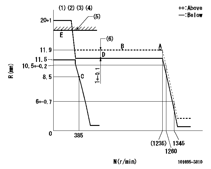
N:Pump speed
R:Rack position (mm)
(1)Target notch: K
(2)Tolerance for racks not indicated: +-0.05mm.
(3)The torque control spring does not operate.
(4)Idle spring not operating.
(5)RACK LIMIT: RAL
(6)Boost compensator stroke
----------
K=7 RAL=15+0.2mm
----------
----------
K=7 RAL=15+0.2mm
----------
Speed control lever angle
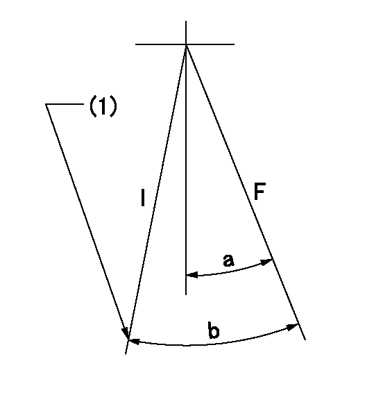
F:Full speed
I:Idle
(1)Stopper bolt setting
----------
----------
a=11deg+-5deg b=27deg+-5deg
----------
----------
a=11deg+-5deg b=27deg+-5deg
Stop lever angle

N:Pump normal
S:Stop the pump.
(1)Pump speed aa and rack position bb (to be sealed at delivery)
----------
aa=0r/min bb=1-0.2mm
----------
a=21deg+-5deg b=(55deg)
----------
aa=0r/min bb=1-0.2mm
----------
a=21deg+-5deg b=(55deg)
Timing setting

(1)Pump vertical direction
(2)Position of key groove at No 1 cylinder's beginning of injection
(3)Stamp aligning marks on the pump housing flange.
(4)-
(5)-
----------
----------
a=59deg36min+-3deg b=0deg24min+-30min
----------
----------
a=59deg36min+-3deg b=0deg24min+-30min
Information:
(1) Gear. If new gear is required, replace camshaft assembly. The heat treatment of the gear is damaged if heated.(2) Diameter of the surfaces (journals) for the camshaft bearings (new) ... 69.850 0.013 mm (2.7500 .0005 in) Bore in front bearing for the camshaft (after assembly) ... 69.969 0.048 mm (2.7547 .0019 in)Bore in the other six bearings for the camshaft (after assembly) ... 69.982 0.061 mm (2.7552 .0024 in)(3) Thickness of thrust plate (new) ... 4.65 0.03 mm (.183 .001 in) End play of the camshaft ... 0.10 to 0.26 mm (.004 to .010 in)(4) Camshaft. (5) Height of camshaft lobes.To find lobe height, use the procedure that follows:A. Measure camshaft lobe height (5).B. Measure base circle (7).C. Subtract base circle (STEP B) from lobe height (STEP A). The difference is actual lobe lift (6).D. Specified camshaft lobe lift (6) is: Camshaft Assemblya. Exhaust lobe ... 10.5 mm (.413 in)b. Inlet lobe ... 10.5 mm (.413 in)Maximum permissible difference between actual lobe lift (STEP C) and specified lobe lift (STEP D) is 0.13 mm (.005 in)Inlet Valve Timing
1. Check the No. 1 inlet valve lash with the engine stopped. The valve lash must be 0.30 to 0.46 mm (.012 to .018 in). If the valve lash is not in this range, adjust the lash to 0.38 mm (.015 in).2. Mark Top Center Position of the crankshaft on the vibration damper or pulley.3. Use a dial indicator to measure the inlet valve movement.4. Rotate the crankshaft in the direction of normal engine rotation. Stop when the inlet valve is 1.91 mm (.075 in) off its seat in the opening sequence.At this point the crankshaft Top Center Position Mark must be ... 5 2 degrees After Top CenterChecking Valve-Camshaft Timing (field procedure)
The following procedure will simplify the checking of the camshaft timing procedures.1. Set the No. 3 inlet bridge adjustment. Refer to SENR6547 (Testing And Adjusting).2. Set the No. 3 inlet valve lash. Refer to SENR6547 (Testing And Adjusting).3. Install the bolt in the flywheel with No. 1 piston at top center.4. Install the dial indicator (magnetic base) to No. 3 inlet bridge.5. Remove the bolt from the flywheel.6. Set the indicator at zero and rotate the engine in the normal direction of operation (counterclockwise as viewed from the flywheel end) until dial travel stops.The correct setting should be ... 14.21 0.25 mm (.560 .010 in)
Have questions with 101695-3810?
Group cross 101695-3810 ZEXEL
Komatsu
101695-3810
INJECTION-PUMP ASSEMBLY