Information injection-pump assembly
BOSCH
9 400 610 222
9400610222
ZEXEL
101695-3580
1016953580
KOMATSU
6206711460
6206711460
Rating:
Service parts 101695-3580 INJECTION-PUMP ASSEMBLY:
1.
_

5.
AUTOM. ADVANCE MECHANIS
6.
COUPLING PLATE
7.
COUPLING PLATE
8.
_
9.
_
11.
Nozzle and Holder
6207-11-3100
12.
Open Pre:MPa(Kqf/cm2)
19.6{200}

15.
NOZZLE SET
Cross reference number
BOSCH
9 400 610 222
9400610222
ZEXEL
101695-3580
1016953580
KOMATSU
6206711460
6206711460
Zexel num
Bosch num
Firm num
Name
101695-3580
9 400 610 222
6206711460 KOMATSU
INJECTION-PUMP ASSEMBLY
6D95L K 14BE INJECTION PUMP ASSY PE6A PE
6D95L K 14BE INJECTION PUMP ASSY PE6A PE
Calibration Data:
Adjustment conditions
Test oil
1404 Test oil ISO4113 or {SAEJ967d}
1404 Test oil ISO4113 or {SAEJ967d}
Test oil temperature
degC
40
40
45
Nozzle and nozzle holder
105780-8140
Bosch type code
EF8511/9A
Nozzle
105780-0000
Bosch type code
DN12SD12T
Nozzle holder
105780-2080
Bosch type code
EF8511/9
Opening pressure
MPa
17.2
Opening pressure
kgf/cm2
175
Injection pipe
Outer diameter - inner diameter - length (mm) mm 6-2-600
Outer diameter - inner diameter - length (mm) mm 6-2-600
Tester oil delivery pressure
kPa
157
157
157
Tester oil delivery pressure
kgf/cm2
1.6
1.6
1.6
Direction of rotation (viewed from drive side)
Right R
Right R
Injection timing adjustment
Direction of rotation (viewed from drive side)
Right R
Right R
Injection order
1-5-3-6-
2-4
Pre-stroke
mm
3.6
3.55
3.65
Beginning of injection position
Drive side NO.1
Drive side NO.1
Difference between angles 1
Cal 1-5 deg. 60 59.5 60.5
Cal 1-5 deg. 60 59.5 60.5
Difference between angles 2
Cal 1-3 deg. 120 119.5 120.5
Cal 1-3 deg. 120 119.5 120.5
Difference between angles 3
Cal 1-6 deg. 180 179.5 180.5
Cal 1-6 deg. 180 179.5 180.5
Difference between angles 4
Cyl.1-2 deg. 240 239.5 240.5
Cyl.1-2 deg. 240 239.5 240.5
Difference between angles 5
Cal 1-4 deg. 300 299.5 300.5
Cal 1-4 deg. 300 299.5 300.5
Injection quantity adjustment
Adjusting point
A
Rack position
10.3
Pump speed
r/min
900
900
900
Average injection quantity
mm3/st.
52
51
53
Max. variation between cylinders
%
0
-2.5
2.5
Basic
*
Fixing the rack
*
Injection quantity adjustment_02
Adjusting point
-
Rack position
9.1+-0.5
Pump speed
r/min
400
400
400
Average injection quantity
mm3/st.
10.5
9.5
11.5
Max. variation between cylinders
%
0
-15
15
Fixing the rack
*
Remarks
Adjust only variation between cylinders; adjust governor according to governor specifications.
Adjust only variation between cylinders; adjust governor according to governor specifications.
Test data Ex:
Governor adjustment
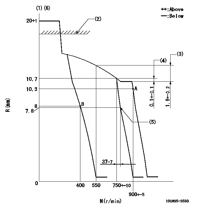
N:Pump speed
R:Rack position (mm)
(1)Target notch: K
(2)RACK CAP: R1
(3)Rack difference between N = N1 and N = N2
(4)Rack difference between N = N3 and N = N4
(5)Idle sub spring setting: L1.
(6)The torque control spring must does not have a set force.
----------
K=8 R1=(17.5)mm N1=800r/min N2=550r/min N3=800r/min N4=750r/min L1=7.8-0.5mm
----------
----------
K=8 R1=(17.5)mm N1=800r/min N2=550r/min N3=800r/min N4=750r/min L1=7.8-0.5mm
----------
Speed control lever angle
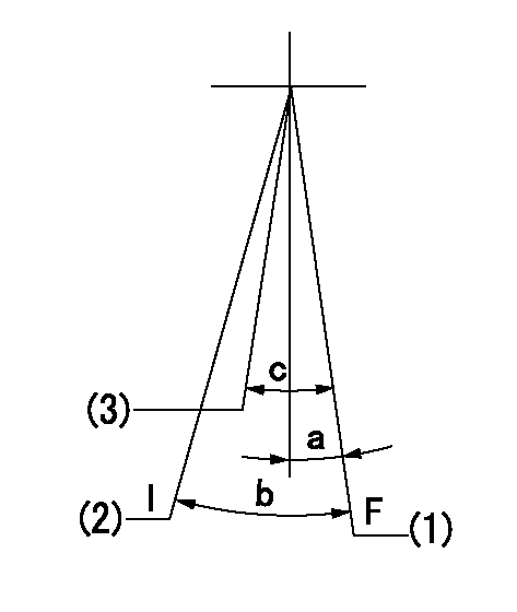
F:Full speed
I:Idle
(1)Set the pump speed at aa. ( At delivery )
(2)Stopper bolt setting
(3)Set the pump speed at bb.
----------
aa=900r/min bb=750r/min
----------
a=(5deg)+-5deg b=(21deg)+-5deg c=(6deg)+-5deg
----------
aa=900r/min bb=750r/min
----------
a=(5deg)+-5deg b=(21deg)+-5deg c=(6deg)+-5deg
Stop lever angle

N:Pump normal
S:Stop the pump.
(1)At delivery
----------
----------
a=26.5deg+-5deg b=53deg+-5deg
----------
----------
a=26.5deg+-5deg b=53deg+-5deg
Timing setting

(1)Pump vertical direction
(2)Position of key groove at No 1 cylinder's beginning of injection
(3)Stamp aligning marks on the pump housing flange.
(4)-
----------
----------
a=59deg36min+-3deg b=0deg24min+-30min
----------
----------
a=59deg36min+-3deg b=0deg24min+-30min
Information:
Start By:a. remove valve cover 1. Remove four bolts (1) that hold each rocker arm assembly in position. Remove the rocker arm assemblies from the engine.2. Put identification marks on all push rods as to their location in the engine. Remove the push rods from the engine. 3. Disassemble the rocker arm assemblies as follows: a. Remove the pin and rocker arm mounts (2). Remove the two rocker arm assemblies and the unit injector arm assembly from the shaft assembly.b. Remove the nut and valve adjusting screw (3) from each rocker arm.c. Remove arm button (7), retaining ring (6) and the arm socket from the unit injector arm.d. Loosen the nut, and remove injection adjusting screw (4) from the unit injector arm.e. Remove sleeve bearing (5) from the unit injector arm. The following steps are for the installation of the rocker arm assemblies and push rods.4. Be sure all parts of the rocker arm assemblies are clean.5. Assemble the rocker arm assemblies as follows: a. Install sleeve bearing (5) in the unit injector arm with Tool (A).b. Install injection adjusting screw (4) and the nut in the unit injector arm.c. Install the arm socket, retaining ring (6) and arm button (7) in the unit injector arm.d. Install valve adjusting screw (3) and the nut in each rocker arm.e. Put the rocker arm assemblies and the unit injector arm assembly in position on the shaft assembly. Install two rocker arm mounts (2) and the pins that hold them.6. Apply clean engine oil to the push rods, and install them in their original locations in the engine. Be sure the push rods are seated in the lifter arm assemblies.7. Loosen all adjusting screws in the rocker arm assemblies. Position the rocker arm assemblies on the cylinder head assembly, and install bolts (1) that hold them in position.8. Adjust the fuel timing and the valve lash. See the topics "Fuel Timing" & "Valve Lash" in the 3114 & 3116 Diesel truck Engines Systems Operation & Testing & Adjusting module, Form No. SENR6437.End By:a. install valve cover
Have questions with 101695-3580?
Group cross 101695-3580 ZEXEL
Komatsu
101695-3580
9 400 610 222
6206711460
INJECTION-PUMP ASSEMBLY
6D95L
6D95L