Information injection-pump assembly
BOSCH
9 400 616 118
9400616118
ZEXEL
101695-3570
1016953570
KOMATSU
6207711820
6207711820

Rating:
Service parts 101695-3570 INJECTION-PUMP ASSEMBLY:
1.
_
5.
AUTOM. ADVANCE MECHANIS
7.
COUPLING PLATE
8.
_
9.
_
11.
Nozzle and Holder
12.
Open Pre:MPa(Kqf/cm2)
19.6{200}

15.
NOZZLE SET
Cross reference number
BOSCH
9 400 616 118
9400616118
ZEXEL
101695-3570
1016953570
KOMATSU
6207711820
6207711820
Zexel num
Bosch num
Firm num
Name
101695-3570
9 400 616 118
6207711820 KOMATSU
INJECTION-PUMP ASSEMBLY
S6D95L K
S6D95L K
Calibration Data:
Adjustment conditions
Test oil
1404 Test oil ISO4113 or {SAEJ967d}
1404 Test oil ISO4113 or {SAEJ967d}
Test oil temperature
degC
40
40
45
Nozzle and nozzle holder
105780-8140
Bosch type code
EF8511/9A
Nozzle
105780-0000
Bosch type code
DN12SD12T
Nozzle holder
105780-2080
Bosch type code
EF8511/9
Opening pressure
MPa
17.2
Opening pressure
kgf/cm2
175
Injection pipe
Outer diameter - inner diameter - length (mm) mm 6-2-600
Outer diameter - inner diameter - length (mm) mm 6-2-600
Tester oil delivery pressure
kPa
157
157
157
Tester oil delivery pressure
kgf/cm2
1.6
1.6
1.6
Direction of rotation (viewed from drive side)
Right R
Right R
Injection timing adjustment
Direction of rotation (viewed from drive side)
Right R
Right R
Injection order
1-5-3-6-
2-4
Pre-stroke
mm
3.6
3.55
3.65
Beginning of injection position
Drive side NO.1
Drive side NO.1
Difference between angles 1
Cal 1-5 deg. 60 59.5 60.5
Cal 1-5 deg. 60 59.5 60.5
Difference between angles 2
Cal 1-3 deg. 120 119.5 120.5
Cal 1-3 deg. 120 119.5 120.5
Difference between angles 3
Cal 1-6 deg. 180 179.5 180.5
Cal 1-6 deg. 180 179.5 180.5
Difference between angles 4
Cyl.1-2 deg. 240 239.5 240.5
Cyl.1-2 deg. 240 239.5 240.5
Difference between angles 5
Cal 1-4 deg. 300 299.5 300.5
Cal 1-4 deg. 300 299.5 300.5
Injection quantity adjustment
Adjusting point
A
Rack position
10.9
Pump speed
r/min
1200
1200
1200
Average injection quantity
mm3/st.
45.3
44.3
46.3
Max. variation between cylinders
%
0
-2.5
2.5
Basic
*
Fixing the lever
*
Injection quantity adjustment_02
Adjusting point
-
Rack position
10.6+-0.
5
Pump speed
r/min
350
350
350
Average injection quantity
mm3/st.
12.5
11.5
13.5
Max. variation between cylinders
%
0
-15
15
Fixing the rack
*
Remarks
Adjust only variation between cylinders; adjust governor according to governor specifications.
Adjust only variation between cylinders; adjust governor according to governor specifications.
Test data Ex:
Governor adjustment
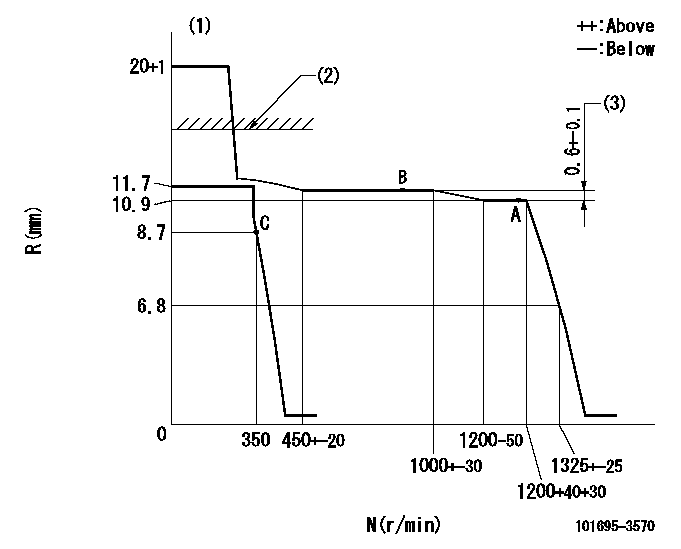
N:Pump speed
R:Rack position (mm)
(1)Target notch: K
(2)RACK LIMIT: RAL
(3)Rack difference between N = N1 and N = N2
----------
K=12 RAL=15+0.2mm N1=1200r/min N2=800r/min
----------
----------
K=12 RAL=15+0.2mm N1=1200r/min N2=800r/min
----------
Speed control lever angle

F:Full speed
I:Idle
(1)Stopper bolt setting
----------
----------
a=17deg+-5deg b=28deg+-5deg
----------
----------
a=17deg+-5deg b=28deg+-5deg
Stop lever angle

N:Pump normal
S:Stop the pump.
----------
----------
a=26.5deg+-5deg b=53deg+-5deg
----------
----------
a=26.5deg+-5deg b=53deg+-5deg
Timing setting

(1)Pump vertical direction
(2)Coupling's key groove position at No 1 cylinder's beginning of injection
(3)-
(4)-
----------
----------
a=(30deg)
----------
----------
a=(30deg)
Information:
Start By:a. remove camshaft 1. Remove eighteen bolts (1) and the washers that hold the front housing to the cylinder block. Remove the front housing. 2. Identify the location of the timing marks on the crankshaft drive gear and the camshaft idler gear assembly.3. Remove camshaft idler gear assembly (2). Remove the sleeve bearing from the camshaft idler gear.4. Remove the three bolts that hold idler shaft (3) to the cylinder block. Remove the idler shaft. The following steps are for the installation of the front housing and idler gear assembly. 5. Using Tool (A) and a press, install the sleeve bearing in the camshaft idler gear. Install the sleeve bearing until it is 0.40 0.25 mm (.016 .010 in) below the front face of the gear.6. Put idler shaft (3) in position on the cylinder block, and install the three bolts that hold it. Tighten the bolts to a torque of 70 15 N m (50 11 lb ft).7. Install camshaft idler gear assembly (2) on the idler shaft with the timing mark facing out. Align the timing marks on the camshaft idler gear with the hole in the crankshaft drive gear.8. Install the front housing as follows: a. Clean the joint face on the front housing with 8T9011 Component Cleaner.b. Apply 6V1541 Quick Cure Primer to the joint face. Allow the primer to dry for three to five minutes minimum.c. Apply 1U8846 Gasket Maker to the joint face. Spread the gasket maker uniformly. The front housing must be installed within ten minutes after application of the gasket maker.
Do not allow the 1U8846 Gasket Maker on the front housing to plug the main oil passage.
9. Put the front housing in position on the cylinder block, and install the eighteen washers and bolts (1) that hold it.End By:a. install camshaft
Do not allow the 1U8846 Gasket Maker on the front housing to plug the main oil passage.
9. Put the front housing in position on the cylinder block, and install the eighteen washers and bolts (1) that hold it.End By:a. install camshaft
Have questions with 101695-3570?
Group cross 101695-3570 ZEXEL
Komatsu
101695-3570
9 400 616 118
6207711820
INJECTION-PUMP ASSEMBLY
S6D95L
S6D95L