Information injection-pump assembly
BOSCH
9 400 616 115
9400616115
ZEXEL
101695-3480
1016953480
KOMATSU
6206711931
6206711931
Rating:
Service parts 101695-3480 INJECTION-PUMP ASSEMBLY:
1.
_
5.
AUTOM. ADVANCE MECHANIS
6.
COUPLING PLATE
7.
COUPLING PLATE
8.
_
9.
_
11.
Nozzle and Holder
12.
Open Pre:MPa(Kqf/cm2)
19.6{200}

15.
NOZZLE SET
Cross reference number
BOSCH
9 400 616 115
9400616115
ZEXEL
101695-3480
1016953480
KOMATSU
6206711931
6206711931
Zexel num
Bosch num
Firm num
Name
101695-3480
9 400 616 115
6206711931 KOMATSU
INJECTION-PUMP ASSEMBLY
6D95L K 14BE INJECTION PUMP ASSY PE6A PE
6D95L K 14BE INJECTION PUMP ASSY PE6A PE
Calibration Data:
Adjustment conditions
Test oil
1404 Test oil ISO4113 or {SAEJ967d}
1404 Test oil ISO4113 or {SAEJ967d}
Test oil temperature
degC
40
40
45
Nozzle and nozzle holder
105780-8140
Bosch type code
EF8511/9A
Nozzle
105780-0000
Bosch type code
DN12SD12T
Nozzle holder
105780-2080
Bosch type code
EF8511/9
Opening pressure
MPa
17.2
Opening pressure
kgf/cm2
175
Injection pipe
Outer diameter - inner diameter - length (mm) mm 6-2-600
Outer diameter - inner diameter - length (mm) mm 6-2-600
Tester oil delivery pressure
kPa
157
157
157
Tester oil delivery pressure
kgf/cm2
1.6
1.6
1.6
Direction of rotation (viewed from drive side)
Right R
Right R
Injection timing adjustment
Direction of rotation (viewed from drive side)
Right R
Right R
Injection order
1-5-3-6-
2-4
Pre-stroke
mm
3.6
3.55
3.65
Beginning of injection position
Drive side NO.1
Drive side NO.1
Difference between angles 1
Cal 1-5 deg. 60 59.5 60.5
Cal 1-5 deg. 60 59.5 60.5
Difference between angles 2
Cal 1-3 deg. 120 119.5 120.5
Cal 1-3 deg. 120 119.5 120.5
Difference between angles 3
Cal 1-6 deg. 180 179.5 180.5
Cal 1-6 deg. 180 179.5 180.5
Difference between angles 4
Cyl.1-2 deg. 240 239.5 240.5
Cyl.1-2 deg. 240 239.5 240.5
Difference between angles 5
Cal 1-4 deg. 300 299.5 300.5
Cal 1-4 deg. 300 299.5 300.5
Injection quantity adjustment
Adjusting point
A
Rack position
10.4
Pump speed
r/min
1350
1350
1350
Average injection quantity
mm3/st.
36.5
35.5
37.5
Max. variation between cylinders
%
0
-2.5
2.5
Basic
*
Fixing the lever
*
Injection quantity adjustment_02
Adjusting point
-
Rack position
10.5+-0.
5
Pump speed
r/min
400
400
400
Average injection quantity
mm3/st.
10.5
9.5
11.5
Max. variation between cylinders
%
0
-15
15
Fixing the rack
*
Remarks
Adjust only variation between cylinders; adjust governor according to governor specifications.
Adjust only variation between cylinders; adjust governor according to governor specifications.
Test data Ex:
Governor adjustment
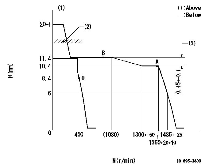
N:Pump speed
R:Rack position (mm)
(1)Target notch: K
(2)RACK LIMIT: RAL
(3)Rack difference between N = N1 and N = N2
----------
K=15 RAL=15+0.2mm N1=1350r/min N2=750r/min
----------
----------
K=15 RAL=15+0.2mm N1=1350r/min N2=750r/min
----------
Speed control lever angle
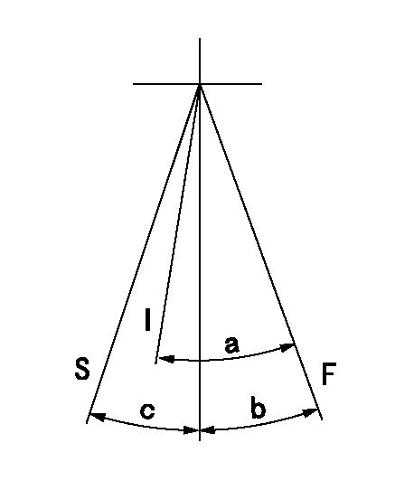
F:Full speed
I:Idle
S:Stop
----------
----------
a=24deg+-5deg b=17deg+-5deg c=32deg+-3deg
----------
----------
a=24deg+-5deg b=17deg+-5deg c=32deg+-3deg
Timing setting

(1)Pump vertical direction
(2)Position of key groove at No 1 cylinder's beginning of injection
(3)Stamp aligning marks on the pump housing flange.
(4)-
(5)-
----------
----------
a=59deg36min+-3deg b=0deg24min+-30min
----------
----------
a=59deg36min+-3deg b=0deg24min+-30min
Information:
At operating temperature, the engine coolant is hot and under pressure. Steam can cause personal injury. Check the coolant level only after the engine has been stopped and the fill cap is cool enough to touch with your bare hand. Remove the fill cap slowly to relieve pressure in the cooling system. Cooling system conditioner contains alkali. Avoid contact with skin and eyes to prevent personal injury.
1. Drain the coolant from the cooling system into a suitable container for storage or disposal. 2. Loosen bolts (1) and (2) on water pump drive (3).3. Remove V-belt (4) from the drive pulley on the water pump and the pulley on the water pump drive.4. Remove two hose clamps (5). Disconnect the hose used between the water pump and the water temperature regulator housing at the water pump.5. Remove four bolts (6) that hold the water pump to the front of the engine. Carefully remove the water pump and two O-ring seals from the front of the engine. The following steps are for the installation of the water pump.6. Check the condition of the two O-ring seals used between the water pump and the cylinder block. If the seals are damaged, use new parts for replacement.7. Install the two O-ring seals in the cover of the water pump. Put the water pump in position on the front of the engine, and install four bolts (6) that hold it.8. Connect the short hose used between the water pump and the water temperature regulator housing to the water pump. Install two clamps (5) that hold the hose in position.9. Put V-belt (4) in position on the water pump drive pulley and the pulley on water pump drive.10. Adjust the tension of water pump drive V-belt (4). Bolt (7) or square hole (8) are used to apply and hold V-belt tension. See the topic "Alternator And Fan Drive Belts, Inspect/Adjust/Replace" in the 3114 & 3116 ATAAC Diesel Truck Engine Operation & Maintenance Manual, Form No. SEBU6723. Also, refer to the "Belt Tension Chart" in the 3114 & 3116 Diesel Truck Engines Specifications module, Form No. SENR6436.11. Fill the cooling system with coolant to the correct level. See the topic "Cooling System" in the 3114 & 3116 ATAAC Diesel Truck Engine Operation & Maintenance Manual, Form No. SEBU6723.Disassemble & Assemble Water Pump
Start By:a. remove water pump 1. Remove two O-ring seals (1) from the rear cover of the water pump. Remove four bolts (2) and the washers. Remove the rear cover and gasket. 2. Put the water pump in a press. Use spacer plates to level the water pump as shown.3. Using a suitable size drive plate from Tool (A) and a press, push the
Have questions with 101695-3480?
Group cross 101695-3480 ZEXEL
Komatsu
101695-3480
9 400 616 115
6206711931
INJECTION-PUMP ASSEMBLY
6D95L
6D95L