Information injection-pump assembly
BOSCH
9 400 616 108
9400616108
ZEXEL
101695-3370
1016953370
KOMATSU
6206711311
6206711311

Rating:
Service parts 101695-3370 INJECTION-PUMP ASSEMBLY:
1.
_
5.
AUTOM. ADVANCE MECHANIS
6.
COUPLING PLATE
7.
COUPLING PLATE
8.
_
9.
_
11.
Nozzle and Holder
12.
Open Pre:MPa(Kqf/cm2)
19.6{200}

15.
NOZZLE SET
Cross reference number
BOSCH
9 400 616 108
9400616108
ZEXEL
101695-3370
1016953370
KOMATSU
6206711311
6206711311
Zexel num
Bosch num
Firm num
Name
101695-3370
9 400 616 108
6206711311 KOMATSU
INJECTION-PUMP ASSEMBLY
6D95L K
6D95L K
Calibration Data:
Adjustment conditions
Test oil
1404 Test oil ISO4113 or {SAEJ967d}
1404 Test oil ISO4113 or {SAEJ967d}
Test oil temperature
degC
40
40
45
Nozzle and nozzle holder
105780-8140
Bosch type code
EF8511/9A
Nozzle
105780-0000
Bosch type code
DN12SD12T
Nozzle holder
105780-2080
Bosch type code
EF8511/9
Opening pressure
MPa
17.2
Opening pressure
kgf/cm2
175
Injection pipe
Outer diameter - inner diameter - length (mm) mm 6-2-600
Outer diameter - inner diameter - length (mm) mm 6-2-600
Tester oil delivery pressure
kPa
157
157
157
Tester oil delivery pressure
kgf/cm2
1.6
1.6
1.6
Direction of rotation (viewed from drive side)
Right R
Right R
Injection timing adjustment
Direction of rotation (viewed from drive side)
Right R
Right R
Injection order
1-5-3-6-
2-4
Pre-stroke
mm
3.6
3.55
3.65
Beginning of injection position
Drive side NO.1
Drive side NO.1
Difference between angles 1
Cal 1-5 deg. 60 59.5 60.5
Cal 1-5 deg. 60 59.5 60.5
Difference between angles 2
Cal 1-3 deg. 120 119.5 120.5
Cal 1-3 deg. 120 119.5 120.5
Difference between angles 3
Cal 1-6 deg. 180 179.5 180.5
Cal 1-6 deg. 180 179.5 180.5
Difference between angles 4
Cyl.1-2 deg. 240 239.5 240.5
Cyl.1-2 deg. 240 239.5 240.5
Difference between angles 5
Cal 1-4 deg. 300 299.5 300.5
Cal 1-4 deg. 300 299.5 300.5
Injection quantity adjustment
Adjusting point
A
Rack position
10.3
Pump speed
r/min
1250
1250
1250
Average injection quantity
mm3/st.
36.7
34.7
38.7
Max. variation between cylinders
%
0
-2.5
2.5
Basic
*
Fixing the lever
*
Injection quantity adjustment_02
Adjusting point
B
Rack position
10.8
Pump speed
r/min
800
800
800
Average injection quantity
mm3/st.
38.6
36.6
40.6
Fixing the lever
*
Injection quantity adjustment_03
Adjusting point
-
Rack position
9.8+-0.5
Pump speed
r/min
400
400
400
Average injection quantity
mm3/st.
8.5
7.5
9.5
Max. variation between cylinders
%
0
-15
15
Fixing the rack
*
Remarks
Adjust only variation between cylinders; adjust governor according to governor specifications.
Adjust only variation between cylinders; adjust governor according to governor specifications.
Test data Ex:
Governor adjustment
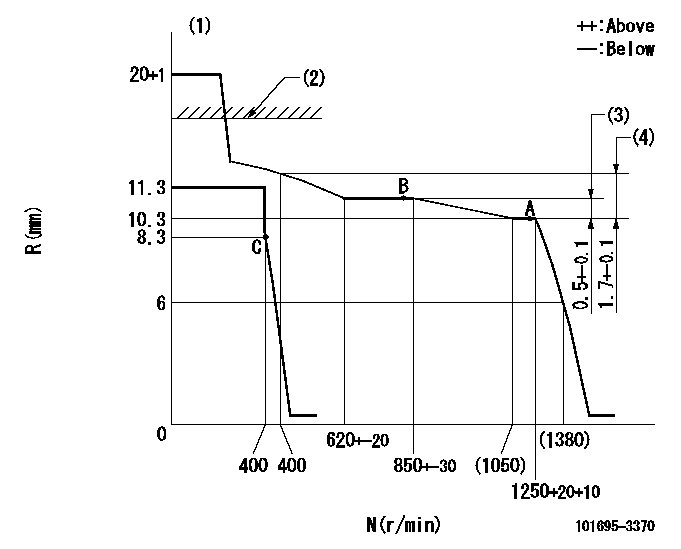
N:Pump speed
R:Rack position (mm)
(1)Notch fixed: K
(2)RACK LIMIT: RAL
(3)Rack difference between N = N1 and N = N2
(4)Rack difference between N = N3 and N = N4
----------
K=20 RAL=15+0.2mm N1=1250r/min N2=800r/min N3=1250r/min N4=400r/min
----------
----------
K=20 RAL=15+0.2mm N1=1250r/min N2=800r/min N3=1250r/min N4=400r/min
----------
Speed control lever angle
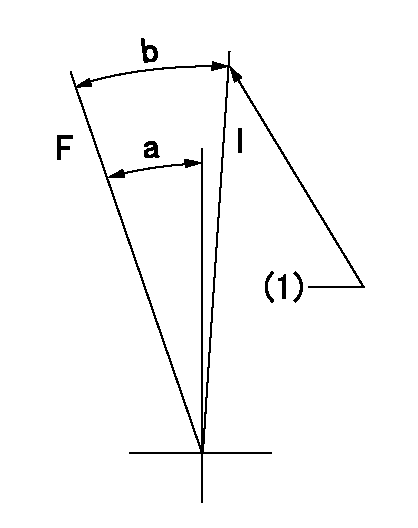
F:Full speed
I:Idle
(1)Stopper bolt setting
----------
----------
a=25deg+-5deg b=28deg+-5deg
----------
----------
a=25deg+-5deg b=28deg+-5deg
Stop lever angle

N:Pump normal
S:Stop the pump.
----------
----------
a=26.5deg+-5deg b=53deg+-5deg
----------
----------
a=26.5deg+-5deg b=53deg+-5deg
Timing setting

(1)Pump vertical direction
(2)Position of key groove at No 1 cylinder's beginning of injection
(3)Stamp aligning marks on the pump housing flange.
(4)-
----------
----------
a=59deg36min+-3deg b=0deg24min+-30min
----------
----------
a=59deg36min+-3deg b=0deg24min+-30min
Information:
1. Remove cylinder head assembly mounting bolts (1) and (2).
To prevent damage to the cylinder head assembly-to-spacer block dowels, keep the head assembly level during removal.
2. Fasten a hoist to the cylinder head assembly as shown. Lift the cylinder head assembly off of the spacer block. The approximate weight of the cylinder head is 236 kg (520 lb).3. Remove the cylinder head assembly gasket from the spacer block. The following steps are for the installation of the cylinder head assembly.4. Thoroughly clean the mating surfaces of the cylinder head assembly and the spacer block.5. Install the head gasket on the spacer block.6. Fasten a hoist to the cylinder head assembly. Position the cylinder head assembly on the dowels in the spacer block. Lower the cylinder head assembly onto the spacer block.7. Put clean engine oil on the threads of bolts (1) and (2) that hold the cylinder head assembly in position. Install bolts (1) and (2).
Cylinder Head Assembly Tightening Sequence8. Tighten cylinder head assembly mounting bolts (1) and (2) as follows:a. Put 2P2506 Thread Lubricant on the threads of bolts (1) and (2).b . Tighten bolts 1 through 26 in numerical sequence shown to a torque of 150 15 N m (110 11 lb ft).c. Tighten bolts 1 through 26 in numerical sequence shown to a torque of 275 15 N m (200 11 lb ft).d. Retorque bolts 1 through 26 in numerical sequence shown to 275 15 N m (200 11 lb ft).e. Tighten bolts 27 through 33 in numerical sequence shown to a torque of 25 7 N m (18 5 lb ft).End By:a. install valve cover baseb. install (EUI) fuel injectorsc. install rocker arm assemblies and push rodsd. install water outlet manifolde. install exhaust manifold
Have questions with 101695-3370?
Group cross 101695-3370 ZEXEL
Komatsu
Komatsu
101695-3370
9 400 616 108
6206711311
INJECTION-PUMP ASSEMBLY
6D95L
6D95L