Information injection-pump assembly
ZEXEL
101695-3330
1016953330
KOMATSU
6206711271
6206711271

Rating:
Cross reference number
ZEXEL
101695-3330
1016953330
KOMATSU
6206711271
6206711271
Zexel num
Bosch num
Firm num
Name
101695-3330
6206711271 KOMATSU
INJECTION-PUMP ASSEMBLY
6D95L * K
6D95L * K
Calibration Data:
Adjustment conditions
Test oil
1404 Test oil ISO4113 or {SAEJ967d}
1404 Test oil ISO4113 or {SAEJ967d}
Test oil temperature
degC
40
40
45
Nozzle and nozzle holder
105780-8140
Bosch type code
EF8511/9A
Nozzle
105780-0000
Bosch type code
DN12SD12T
Nozzle holder
105780-2080
Bosch type code
EF8511/9
Opening pressure
MPa
17.2
Opening pressure
kgf/cm2
175
Injection pipe
Outer diameter - inner diameter - length (mm) mm 6-2-600
Outer diameter - inner diameter - length (mm) mm 6-2-600
Tester oil delivery pressure
kPa
157
157
157
Tester oil delivery pressure
kgf/cm2
1.6
1.6
1.6
Direction of rotation (viewed from drive side)
Right R
Right R
Injection timing adjustment
Direction of rotation (viewed from drive side)
Right R
Right R
Injection order
1-5-3-6-
2-4
Pre-stroke
mm
3.6
3.55
3.65
Beginning of injection position
Drive side NO.1
Drive side NO.1
Difference between angles 1
Cal 1-5 deg. 60 59.5 60.5
Cal 1-5 deg. 60 59.5 60.5
Difference between angles 2
Cal 1-3 deg. 120 119.5 120.5
Cal 1-3 deg. 120 119.5 120.5
Difference between angles 3
Cal 1-6 deg. 180 179.5 180.5
Cal 1-6 deg. 180 179.5 180.5
Difference between angles 4
Cyl.1-2 deg. 240 239.5 240.5
Cyl.1-2 deg. 240 239.5 240.5
Difference between angles 5
Cal 1-4 deg. 300 299.5 300.5
Cal 1-4 deg. 300 299.5 300.5
Injection quantity adjustment
Adjusting point
A
Rack position
10.4
Pump speed
r/min
1050
1050
1050
Average injection quantity
mm3/st.
34.8
33.8
35.8
Max. variation between cylinders
%
0
-2.5
2.5
Basic
*
Fixing the lever
*
Injection quantity adjustment_02
Adjusting point
B
Rack position
10.5+-0.
5
Pump speed
r/min
400
400
400
Average injection quantity
mm3/st.
10.5
9.5
11.5
Max. variation between cylinders
%
0
-15
15
Fixing the rack
*
Remarks
Adjust only variation between cylinders; adjust governor according to governor specifications.
Adjust only variation between cylinders; adjust governor according to governor specifications.
Test data Ex:
Governor adjustment
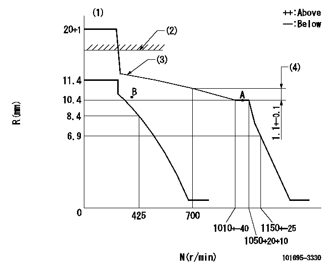
N:Pump speed
R:Rack position (mm)
(1)Target notch: K
(2)RACK LIMIT: RAL
(3)The torque control spring must does not have a set force.
(4)Rack difference between N = N1 and N = N2
----------
K=14 RAL=15+0.2mm N1=1050r/min N2=700r/min
----------
----------
K=14 RAL=15+0.2mm N1=1050r/min N2=700r/min
----------
Speed control lever angle

F:Full speed
I:Idle
S:Stop
----------
----------
a=11deg+-5deg b=32deg+-3deg c=20deg+-5deg
----------
----------
a=11deg+-5deg b=32deg+-3deg c=20deg+-5deg
Timing setting

(1)Pump vertical direction
(2)Coupling's key groove position at No 1 cylinder's beginning of injection
(3)-
(4)-
----------
----------
a=(30deg)
----------
----------
a=(30deg)
Information:
1. Using tool (A), remove oil filter assembly (1). 2. Remove two bolts (4) and the washers.3. Remove four bolts (3) and the washers.4. Remove six bolts (2) and the washers. Remove the oil filter base assembly, gaskets and O-ring seals. The following steps are for the installation of the oil filter base assembly and the oil filter.5. Check the condition of the O-ring seals and gaskets used for installation of the oil filter base assembly. If any of the seals or gaskets are worn or damaged, use new parts for replacement. Position all gaskets, and install all bolts finger tight before tightening them to the standard torque value.6. Install the O-ring seals in the oil filter base assembly. Put all gaskets and the oil filter base assembly in position on the cylinder block. Install six bolts (2) and the washers that hold it.7. Install four bolts (3) and the washers.8. Position the gasket. Install two bolts (4) and the washers. Tighten all the bolts to standard torque value.9. Install oil filter assembly (1). Follow the instructions with the oil filter assembly for correct installation.Disassemble & Assemble Oil Filter Base Assembly
Start By:a. remove oil filter and oil filter base assembly 1. Remove three O-ring seals (1) from the oil filter base.2. Remove relief valve assembly (2) as follows: a. Slowly loosen bolt (6) to release compression on spring (4).b. Remove bolt (6), relief valve spring seat (5), spring (4) and retainer (3) from the oil filter base. Remove spacer (7) from bolt (6). 3. Remove oil filter bypass valve (8), oil cooler base valve (9) and oil filter bypass valve (10) from the oil filter base as follows: a. Remove oil filter bypass valve (8). Remove plug (11), spring (13) and plunger (14) from the oil filter base. Remove O-ring seal (12) from plug (11). b. Remove oil cooler base valve (9) from the oil filter base. Remove the two bolts and washers that hold oil cooler base valve (9) in position. Remove oil cooler base valve (9). Remove the O-ring seal from the oil filter base. c. Remove oil filter bypass valve (10) from the oil filter base. Slowly remove the two bolts and washers that hold cover (15) in place to release the spring compression. Remove cover (15) and the O-ring seal from the oil filter base. Remove spring assembly (16) and bypass valve (17) from the oil filter base.4. If necessary, remove the stud that holds the oil filter to the oil filter base. The following steps are for the assembly of the oil filter base assembly.5. Be sure all parts of the oil filter base assembly are thoroughly clean prior to assembly. Check the condition of all O-ring seals prior to assembly of the oil filter base assembly. If any of the seals are worn or damaged, use new parts for replacement.6. If the stud which holds the oil filter to the oil filter base was removed, reinstall it. Tighten the stud to
Start By:a. remove oil filter and oil filter base assembly 1. Remove three O-ring seals (1) from the oil filter base.2. Remove relief valve assembly (2) as follows: a. Slowly loosen bolt (6) to release compression on spring (4).b. Remove bolt (6), relief valve spring seat (5), spring (4) and retainer (3) from the oil filter base. Remove spacer (7) from bolt (6). 3. Remove oil filter bypass valve (8), oil cooler base valve (9) and oil filter bypass valve (10) from the oil filter base as follows: a. Remove oil filter bypass valve (8). Remove plug (11), spring (13) and plunger (14) from the oil filter base. Remove O-ring seal (12) from plug (11). b. Remove oil cooler base valve (9) from the oil filter base. Remove the two bolts and washers that hold oil cooler base valve (9) in position. Remove oil cooler base valve (9). Remove the O-ring seal from the oil filter base. c. Remove oil filter bypass valve (10) from the oil filter base. Slowly remove the two bolts and washers that hold cover (15) in place to release the spring compression. Remove cover (15) and the O-ring seal from the oil filter base. Remove spring assembly (16) and bypass valve (17) from the oil filter base.4. If necessary, remove the stud that holds the oil filter to the oil filter base. The following steps are for the assembly of the oil filter base assembly.5. Be sure all parts of the oil filter base assembly are thoroughly clean prior to assembly. Check the condition of all O-ring seals prior to assembly of the oil filter base assembly. If any of the seals are worn or damaged, use new parts for replacement.6. If the stud which holds the oil filter to the oil filter base was removed, reinstall it. Tighten the stud to
Have questions with 101695-3330?
Group cross 101695-3330 ZEXEL
Komatsu
101695-3330
6206711271
INJECTION-PUMP ASSEMBLY
6D95L
6D95L