Information injection-pump assembly
BOSCH
9 400 616 096
9400616096
ZEXEL
101695-3152
1016953152
KOMATSU
6207711411
6207711411
Rating:
Service parts 101695-3152 INJECTION-PUMP ASSEMBLY:
1.
_
5.
AUTOM. ADVANCE MECHANIS
6.
COUPLING PLATE
7.
COUPLING PLATE
8.
_
9.
_
11.
Nozzle and Holder
6207-11-3102
12.
Open Pre:MPa(Kqf/cm2)
19.6{200}
15.
NOZZLE SET
Cross reference number
BOSCH
9 400 616 096
9400616096
ZEXEL
101695-3152
1016953152
KOMATSU
6207711411
6207711411
Zexel num
Bosch num
Firm num
Name
101695-3152
9 400 616 096
6207711411 KOMATSU
INJECTION-PUMP ASSEMBLY
S6D95L K 14BE INJECTION PUMP ASSY PE6A PE
S6D95L K 14BE INJECTION PUMP ASSY PE6A PE
Calibration Data:
Adjustment conditions
Test oil
1404 Test oil ISO4113 or {SAEJ967d}
1404 Test oil ISO4113 or {SAEJ967d}
Test oil temperature
degC
40
40
45
Nozzle and nozzle holder
105780-8140
Bosch type code
EF8511/9A
Nozzle
105780-0000
Bosch type code
DN12SD12T
Nozzle holder
105780-2080
Bosch type code
EF8511/9
Opening pressure
MPa
17.2
Opening pressure
kgf/cm2
175
Injection pipe
Outer diameter - inner diameter - length (mm) mm 6-2-600
Outer diameter - inner diameter - length (mm) mm 6-2-600
Tester oil delivery pressure
kPa
157
157
157
Tester oil delivery pressure
kgf/cm2
1.6
1.6
1.6
Direction of rotation (viewed from drive side)
Right R
Right R
Injection timing adjustment
Direction of rotation (viewed from drive side)
Right R
Right R
Injection order
1-5-3-6-
2-4
Pre-stroke
mm
3.6
3.55
3.65
Beginning of injection position
Drive side NO.1
Drive side NO.1
Difference between angles 1
Cal 1-5 deg. 60 59.5 60.5
Cal 1-5 deg. 60 59.5 60.5
Difference between angles 2
Cal 1-3 deg. 120 119.5 120.5
Cal 1-3 deg. 120 119.5 120.5
Difference between angles 3
Cal 1-6 deg. 180 179.5 180.5
Cal 1-6 deg. 180 179.5 180.5
Difference between angles 4
Cyl.1-2 deg. 240 239.5 240.5
Cyl.1-2 deg. 240 239.5 240.5
Difference between angles 5
Cal 1-4 deg. 300 299.5 300.5
Cal 1-4 deg. 300 299.5 300.5
Injection quantity adjustment
Adjusting point
A
Rack position
12.2
Pump speed
r/min
750
750
750
Average injection quantity
mm3/st.
62.7
61.7
63.7
Max. variation between cylinders
%
0
-2.5
2.5
Basic
*
Fixing the lever
*
Injection quantity adjustment_02
Adjusting point
-
Rack position
10+-0.5
Pump speed
r/min
400
400
400
Average injection quantity
mm3/st.
12.5
11.5
13.5
Max. variation between cylinders
%
0
-15
15
Fixing the rack
*
Remarks
Adjust only variation between cylinders; adjust governor according to governor specifications.
Adjust only variation between cylinders; adjust governor according to governor specifications.
Test data Ex:
Governor adjustment
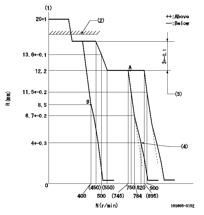
N:Pump speed
R:Rack position (mm)
(1)Target notch: K
(2)RACK CAP: R1
(3)Rack difference between N = N1 and N = N2
(4)Set idle sub-spring
----------
K=12 R1=(17.5)mm N1=750r/min N2=400r/min
----------
----------
K=12 R1=(17.5)mm N1=750r/min N2=400r/min
----------
Speed control lever angle
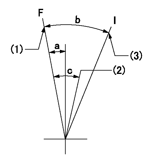
F:Full speed
I:Idle
(1)Set the speed at aa (set the stopper bolt).
(2)Set the pump speed at bb.
(3)Stopper bolt setting
----------
aa=900r/min bb=750r/min
----------
a=(1deg)+-5deg b=(23deg)+-5deg c=(7deg)+-5deg
----------
aa=900r/min bb=750r/min
----------
a=(1deg)+-5deg b=(23deg)+-5deg c=(7deg)+-5deg
Stop lever angle

N:Pump normal
S:Stop the pump.
(1)At delivery
----------
----------
a=26.5deg+-5deg b=53deg+-5deg
----------
----------
a=26.5deg+-5deg b=53deg+-5deg
Timing setting

(1)Pump vertical direction
(2)Position of key groove at No 1 cylinder's beginning of injection
(3)Stamp aligning marks on the pump housing flange.
(4)-
----------
----------
a=59deg36min+-3deg b=0deg24min+-30min
----------
----------
a=59deg36min+-3deg b=0deg24min+-30min
Information:
1. Disconnect plug P14 from receptacle J14. The locking ring helps identify P14 from J14. Check the connections for damaged wires or pins and corrosion. Also check that the pins are at the proper height in the connector. Check that the wires and pins are tight in the connectors by pulling (slightly) on each wire of each connector (including the breakout "T").2. Install 8T8694 Adapter (five pin breakout "T") between J14 and P14. Twist the locking rings to secure the connections.3. Connect the voltmeter as shown. Check for the appropriate voltages between the lettered "T" pins as explained in Steps 4 through 7.4. Pin A (+) to pin B (ground) system voltage should be approximately 12 volts DC with key on (no accessories). Minimum voltage is 11.0 volts DC. Diagnosis - Using the truck wiring schematic, check wires A and B and connections from J14 through the truck wiring harness back to the battery for proper voltage.5. If the voltage check between pins A and B is less than 11.0 volts with the key on, check the voltage drop from pin B to the negative battery post while cranking. For this test, the common lead (black) should be connected to the negative battery post first. Then place the positive (red) lead into pin B. (Pin B is chassis ground.) Voltage should be less than .5 volts DC when cranking. Diagnosis - If the voltage drop is greater than .5 volts DC, check wire B and connections (including the battery post connections) from J14 to battery negative. Follow the truck wiring schematic to trace the electrical path from J14 Pin B to chassis ground.6. Check buffer operation. Step 6 checks the proper functioning of the truck wiring, vehicle speed sensor and vehicle speed buffer. If proper vehicle speed is present on the appropriate status screens of the 3406B (PEEC III) (7X6400) DDT or the (8T8697) ECAP service tools during road test then Step 6 is not necessary.A. Check wires and connectors for damage or corrosion from the magnetic pickup to vehicle speed buffer.B. Remove magnetic pickup (vehicle speed sensor) from transmission. If pickup has collected significant metal debris, wipe it clean. Check the magnetic pickup per the manufactures specifications. Install a properly functioning magnetic pickup to the proper depth and reconnect to the vehicle speed buffer. Check for proper system operation. The problem may reappear if transmission fluid is contaminated. Change transmission fluid if necessary.C.1. Disconnect the magnetic pickup from the vehicle speed buffer.C.2. Jumper the white vehicle speed buffer wire (input from magnetic pickup) to J14 Pin A (+ battery) at the breakout "T".* Voltage from pins D to B of breakout "T" is less than 1.0 volt DC with key on and engine off.* Voltage from pins C to B is -8.0 to -10.0 volts DC with key on.* Voltage from pins E to B is +8.0 to +10.0 volts DC with key on.C.3. Move the white input wire (jumper) to J14 Pin B (- battery)
Have questions with 101695-3152?
Group cross 101695-3152 ZEXEL
Komatsu
Komatsu
101695-3152
9 400 616 096
6207711411
INJECTION-PUMP ASSEMBLY
S6D95L
S6D95L