Information injection-pump assembly
BOSCH
9 400 616 089
9400616089
ZEXEL
101695-3060
1016953060
KOMATSU
6207721261
6207721261

Rating:
Include in #1:
106671-2570
as _
Cross reference number
BOSCH
9 400 616 089
9400616089
ZEXEL
101695-3060
1016953060
KOMATSU
6207721261
6207721261
Zexel num
Bosch num
Firm num
Name
101695-3060
9 400 616 089
6207721261 KOMATSU
INJECTION-PUMP ASSEMBLY
S6D95L K 14BE INJECTION PUMP ASSY PE6A PE
S6D95L K 14BE INJECTION PUMP ASSY PE6A PE
Calibration Data:
Adjustment conditions
Test oil
1404 Test oil ISO4113 or {SAEJ967d}
1404 Test oil ISO4113 or {SAEJ967d}
Test oil temperature
degC
40
40
45
Nozzle and nozzle holder
105780-8140
Bosch type code
EF8511/9A
Nozzle
105780-0000
Bosch type code
DN12SD12T
Nozzle holder
105780-2080
Bosch type code
EF8511/9
Opening pressure
MPa
17.2
Opening pressure
kgf/cm2
175
Injection pipe
Outer diameter - inner diameter - length (mm) mm 6-2-600
Outer diameter - inner diameter - length (mm) mm 6-2-600
Overflow valve
131424-7420
Overflow valve opening pressure
kPa
255
221
289
Overflow valve opening pressure
kgf/cm2
2.6
2.25
2.95
Tester oil delivery pressure
kPa
157
157
157
Tester oil delivery pressure
kgf/cm2
1.6
1.6
1.6
Direction of rotation (viewed from drive side)
Right R
Right R
Injection timing adjustment
Direction of rotation (viewed from drive side)
Right R
Right R
Injection order
1-5-3-6-
2-4
Pre-stroke
mm
3.2
3.15
3.25
Beginning of injection position
Drive side NO.1
Drive side NO.1
Difference between angles 1
Cal 1-5 deg. 60 59.5 60.5
Cal 1-5 deg. 60 59.5 60.5
Difference between angles 2
Cal 1-3 deg. 120 119.5 120.5
Cal 1-3 deg. 120 119.5 120.5
Difference between angles 3
Cal 1-6 deg. 180 179.5 180.5
Cal 1-6 deg. 180 179.5 180.5
Difference between angles 4
Cyl.1-2 deg. 240 239.5 240.5
Cyl.1-2 deg. 240 239.5 240.5
Difference between angles 5
Cal 1-4 deg. 300 299.5 300.5
Cal 1-4 deg. 300 299.5 300.5
Injection quantity adjustment
Adjusting point
A
Rack position
9.8
Pump speed
r/min
1025
1025
1025
Average injection quantity
mm3/st.
69.2
68.2
70.2
Max. variation between cylinders
%
0
-2.5
2.5
Basic
*
Fixing the lever
*
Boost pressure
kPa
32
32
Boost pressure
mmHg
240
240
Injection quantity adjustment_02
Adjusting point
-
Rack position
7.8+-0.5
Pump speed
r/min
450
450
450
Average injection quantity
mm3/st.
12.5
11.5
13.5
Max. variation between cylinders
%
0
-15
15
Fixing the rack
*
Boost pressure
kPa
0
0
0
Boost pressure
mmHg
0
0
0
Remarks
Adjust only variation between cylinders; adjust governor according to governor specifications.
Adjust only variation between cylinders; adjust governor according to governor specifications.
Boost compensator adjustment
Pump speed
r/min
500
500
500
Rack position
R1-1.2
Boost pressure
kPa
9.3
9.3
9.3
Boost pressure
mmHg
70
70
70
Boost compensator adjustment_02
Pump speed
r/min
500
500
500
Rack position
R1(10.1)
Boost pressure
kPa
21.3
17.3
25.3
Boost pressure
mmHg
160
130
190
Test data Ex:
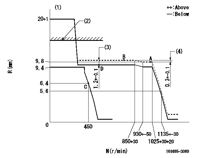
Governor adjustment

N:Pump speed
R:Rack position (mm)
(1)Target notch: K
(2)RACK LIMIT: RAL
(3)Boost compensator stroke
(4)Rack difference between N = N1 and N = N2
----------
K=15 RAL=12.5+0.2mm N1=1025r/min N2=750r/min
----------
----------
K=15 RAL=12.5+0.2mm N1=1025r/min N2=750r/min
----------
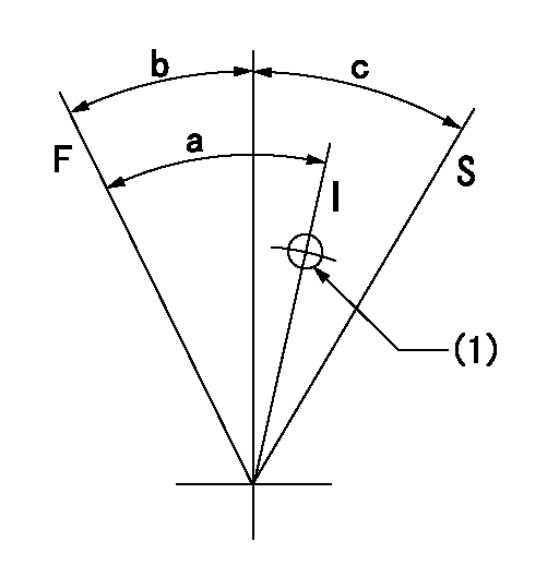
Speed control lever angle

F:Full speed
I:Idle
S:Stop
(1)Use the hole at R = aa
----------
aa=80mm
----------
a=30deg+-5deg b=18deg+-3deg c=32deg+-3deg
----------
aa=80mm
----------
a=30deg+-5deg b=18deg+-3deg c=32deg+-3deg
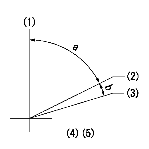
Timing setting

(1)Pump vertical direction
(2)Position of key groove at No 1 cylinder's beginning of injection
(3)Stamp aligning marks on the pump housing flange.
(4)-
(5)-
----------
----------
a=58deg+-3deg b=2deg+-30min
----------
----------
a=58deg+-3deg b=2deg+-30min
Information:
Start By:a. remove oil pump1. Check the main bearing caps for identification for their location and direction in the block. The caps must be installed in the same location and direction from which they were removed. 2. Remove No. 2 through No. 6 bearing caps (1). Remove thrust plates from the No. 4 main bearing.
If the crankshaft is turned in the wrong direction, the tab of the bearing will be pushed between the crankshaft and cylinder block. This can cause damage to either the crankshaft or cylinder block or both.
3. Remove the upper halves of the main bearings by putting tool (A) in oil hole (2) in the crankshaft. Turn the crankshaft in the direction which will push the
Have questions with 101695-3060?
Group cross 101695-3060 ZEXEL
Komatsu
101695-3060
9 400 616 089
6207721261
INJECTION-PUMP ASSEMBLY
S6D95L
S6D95L