Information injection-pump assembly
ZEXEL
101693-9521
1016939521

Rating:
Service parts 101693-9521 INJECTION-PUMP ASSEMBLY:
1.
_
7.
COUPLING PLATE
8.
_
9.
_
11.
Nozzle and Holder
16600-Z5601
12.
Open Pre:MPa(Kqf/cm2)
19.6{200}
15.
NOZZLE SET
Cross reference number
ZEXEL
101693-9521
1016939521
Zexel num
Bosch num
Firm num
Name
101693-9521
INJECTION-PUMP ASSEMBLY
Calibration Data:
Adjustment conditions
Test oil
1404 Test oil ISO4113 or {SAEJ967d}
1404 Test oil ISO4113 or {SAEJ967d}
Test oil temperature
degC
40
40
45
Nozzle and nozzle holder
105780-8140
Bosch type code
EF8511/9A
Nozzle
105780-0000
Bosch type code
DN12SD12T
Nozzle holder
105780-2080
Bosch type code
EF8511/9
Opening pressure
MPa
17.2
Opening pressure
kgf/cm2
175
Injection pipe
Outer diameter - inner diameter - length (mm) mm 6-2-600
Outer diameter - inner diameter - length (mm) mm 6-2-600
Overflow valve
134424-1520
Overflow valve opening pressure
kPa
162
147
177
Overflow valve opening pressure
kgf/cm2
1.65
1.5
1.8
Tester oil delivery pressure
kPa
157
157
157
Tester oil delivery pressure
kgf/cm2
1.6
1.6
1.6
Direction of rotation (viewed from drive side)
Right R
Right R
Injection timing adjustment
Direction of rotation (viewed from drive side)
Right R
Right R
Injection order
1-4-2-6-
3-5
Pre-stroke
mm
3.9
3.85
3.95
Beginning of injection position
Drive side NO.1
Drive side NO.1
Difference between angles 1
Cal 1-4 deg. 60 59.5 60.5
Cal 1-4 deg. 60 59.5 60.5
Difference between angles 2
Cyl.1-2 deg. 120 119.5 120.5
Cyl.1-2 deg. 120 119.5 120.5
Difference between angles 3
Cal 1-6 deg. 180 179.5 180.5
Cal 1-6 deg. 180 179.5 180.5
Difference between angles 4
Cal 1-3 deg. 240 239.5 240.5
Cal 1-3 deg. 240 239.5 240.5
Difference between angles 5
Cal 1-5 deg. 300 299.5 300.5
Cal 1-5 deg. 300 299.5 300.5
Injection quantity adjustment
Adjusting point
-
Rack position
12.6
Pump speed
r/min
700
700
700
Average injection quantity
mm3/st.
80.8
78.8
82.8
Max. variation between cylinders
%
0
-3.5
3.5
Basic
*
Fixing the rack
*
Standard for adjustment of the maximum variation between cylinders
*
Injection quantity adjustment_02
Adjusting point
H
Rack position
9.5+-0.5
Pump speed
r/min
275
275
275
Average injection quantity
mm3/st.
9.6
7.8
11.4
Max. variation between cylinders
%
0
-10
10
Fixing the rack
*
Standard for adjustment of the maximum variation between cylinders
*
Injection quantity adjustment_03
Adjusting point
A
Rack position
R1(12.6)
Pump speed
r/min
700
700
700
Average injection quantity
mm3/st.
80.8
79.8
81.8
Basic
*
Fixing the lever
*
Boost pressure
kPa
21.3
21.3
Boost pressure
mmHg
160
160
Injection quantity adjustment_04
Adjusting point
B
Rack position
R1+0.05
Pump speed
r/min
1400
1400
1400
Average injection quantity
mm3/st.
91.5
88.3
94.7
Fixing the lever
*
Boost pressure
kPa
21.3
21.3
Boost pressure
mmHg
160
160
Injection quantity adjustment_05
Adjusting point
C
Rack position
R2(R1-0.
1)
Pump speed
r/min
550
550
550
Average injection quantity
mm3/st.
76.4
73.2
79.6
Fixing the lever
*
Boost pressure
kPa
21.3
21.3
Boost pressure
mmHg
160
160
Injection quantity adjustment_06
Adjusting point
D
Rack position
R2-0.4
Pump speed
r/min
550
550
550
Average injection quantity
mm3/st.
67
65
69
Fixing the lever
*
Boost pressure
kPa
0
0
0
Boost pressure
mmHg
0
0
0
Injection quantity adjustment_07
Adjusting point
I
Rack position
-
Pump speed
r/min
150
150
150
Average injection quantity
mm3/st.
84
84
104
Fixing the lever
*
Boost pressure
kPa
0
0
0
Boost pressure
mmHg
0
0
0
Rack limit
*
Boost compensator adjustment
Pump speed
r/min
550
550
550
Rack position
R2-0.4
Boost pressure
kPa
4
2.7
5.3
Boost pressure
mmHg
30
20
40
Boost compensator adjustment_02
Pump speed
r/min
550
550
550
Rack position
R2(R1-0.
1)
Boost pressure
kPa
8
8
8
Boost pressure
mmHg
60
60
60
Timer adjustment
Pump speed
r/min
1170--
Advance angle
deg.
0
0
0
Remarks
Start
Start
Timer adjustment_02
Pump speed
r/min
1120
Advance angle
deg.
0.5
Timer adjustment_03
Pump speed
r/min
1400
Advance angle
deg.
3
2.5
3.5
Remarks
Finish
Finish
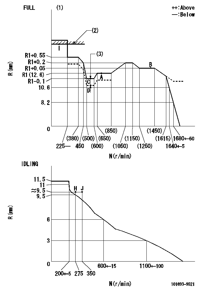
Test data Ex:
Governor adjustment

N:Pump speed
R:Rack position (mm)
(1)Torque cam stamping: T1
(2)RACK LIMIT
(3)Boost compensator stroke: BCL
----------
T1=G33 BCL=0.4+-0.1mm
----------
----------
T1=G33 BCL=0.4+-0.1mm
----------
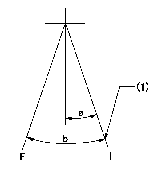
Speed control lever angle

F:Full speed
I:Idle
(1)Stopper bolt set position 'H'
----------
----------
a=26.5deg+-5deg b=(48deg)+-3deg
----------
----------
a=26.5deg+-5deg b=(48deg)+-3deg
Stop lever angle

N:Pump normal
S:Stop the pump.
----------
----------
a=20deg+-5deg b=40deg+-5deg
----------
----------
a=20deg+-5deg b=40deg+-5deg
Timing setting

(1)Pump vertical direction
(2)Position of timer's threaded hole at No 1 cylinder's beginning of injection
(3)-
(4)-
----------
----------
a=(60deg)
----------
----------
a=(60deg)
Information:
Step 7
7. Possible Causes-Engine Will Not StartA. No Fuel In Tank(s)Visually check fuel level in the tank(s). Be sure the tank selection valve is open for the tank with fuel in it. Be sure the fuel line between the tanks (if more than one) is open.B. No Fuel From Unit Injectors1. Prime the fuel system per item 6B.2. If temperatures are below -12° C (10° F), a poor quality fuel can "wax" and cause a restriction in the system. Install a new fuel filter. It may be necessary to drain the entire fuel system and replace with No. 1 grade fuel, or a blend of fuel depending on the air temperature.3. Check for a fuel supply line restriction by removing the fuel supply line from the fuel filter base. Put 35 kPa (5 psi) of air pressure to the fuel tank.
Do not use more than 55 kPa (8 psi) of air pressure in the fuel tank or damage to the tank may result.
If there is no flow or a weak flow of fuel from the supply line, clean or replace plugged lines.4. Check fuel transfer pump pumping gears and drive gear on the camshaft. Repair or replace as necessary. See 3176 Diesel Truck Engine Disassembly and Assembly, Form No. SENR3914.5. Drain the fuel manifold, remove each unit injector (see 3176 Diesel Truck Engine Disassembly and Assembly, Form No. SENR3914) and bench test unit injectors to check flow. Replace plugged unit injectors.Testing of the injectors must be done off of the engine. Use the 1U6661 Pop (Injector) Tester Group with a 1U6663 Injector Holding Block, and a 1U6665 Power Supply, to test the injectors. For the test procedure refer to Special Instruction, Form No. SEHS8867, Using The 1U6661 Pop (Injector) Tester. For test specifications refer to Special Instruction, Form No. SEHS8804, Unit Injector Test Specifications for 1.7 Liter Engines. Inspect and repair as necessary the sealing surface (seat) of the injector sleeve in the cylinder head when removing and installing an injector. The injector sealing surface (seat) must be free of scratches or evidence of combustion products. If it is necessary to rework (ream) or replace the sleeve use 4C4054 Tool Group and refer to Special Instruction, Form No. SEHS9120, Removal And Installation Of Unit Injector Sleeve.C. Restriction In Exhaust SystemLoosen the exhaust pipe from the exhaust manifold and start engine. If the engine starts easily, check the exhaust system for damage and/or restrictions.D. Electrical Problem Ahead Of Electronic Control Module (ECM)Check for a problem with the electrical supply to the ECM.Crankshaft Does Not Turn
Step 8
Possible Causes-Engine Will Not StartA. No Battery VoltageCheck battery voltage. If there is no battery voltage, put a charge to the battery. If battery will not hold a charge, load test the battery. Use the 6V4930 Battery Load Tester and make reference to Special Instruction, Form No. SEHS8268 for complete information on use of the 6V4930 Battery Load Tester.B. Defective Switch, Defective Wiring Or Connection In Switch CircuitWith the ignition switch in the "start"
Have questions with 101693-9521?
Group cross 101693-9521 ZEXEL
Nissan-Diesel
Nissan-Diesel
101693-9521
INJECTION-PUMP ASSEMBLY
