Information injection-pump assembly
ZEXEL
101693-9340
1016939340
Rating:
Service parts 101693-9340 INJECTION-PUMP ASSEMBLY:
1.
_
7.
COUPLING PLATE
8.
_
9.
_
11.
Nozzle and Holder
16600Z5578
12.
Open Pre:MPa(Kqf/cm2)
16.7(170)/21.6(220)
15.
NOZZLE SET
Cross reference number
ZEXEL
101693-9340
1016939340
Zexel num
Bosch num
Firm num
Name
101693-9340
INJECTION-PUMP ASSEMBLY
Calibration Data:
Adjustment conditions
Test oil
1404 Test oil ISO4113 or {SAEJ967d}
1404 Test oil ISO4113 or {SAEJ967d}
Test oil temperature
degC
40
40
45
Nozzle and nozzle holder
105780-8140
Bosch type code
EF8511/9A
Nozzle
105780-0000
Bosch type code
DN12SD12T
Nozzle holder
105780-2080
Bosch type code
EF8511/9
Opening pressure
MPa
17.2
Opening pressure
kgf/cm2
175
Injection pipe
Outer diameter - inner diameter - length (mm) mm 6-2-600
Outer diameter - inner diameter - length (mm) mm 6-2-600
Overflow valve
134424-1520
Overflow valve opening pressure
kPa
162
147
177
Overflow valve opening pressure
kgf/cm2
1.65
1.5
1.8
Tester oil delivery pressure
kPa
157
157
157
Tester oil delivery pressure
kgf/cm2
1.6
1.6
1.6
Direction of rotation (viewed from drive side)
Right R
Right R
Injection timing adjustment
Direction of rotation (viewed from drive side)
Right R
Right R
Injection order
1-4-2-6-
3-5
Pre-stroke
mm
3.9
3.85
3.95
Beginning of injection position
Drive side NO.1
Drive side NO.1
Difference between angles 1
Cal 1-4 deg. 60 59.5 60.5
Cal 1-4 deg. 60 59.5 60.5
Difference between angles 2
Cyl.1-2 deg. 120 119.5 120.5
Cyl.1-2 deg. 120 119.5 120.5
Difference between angles 3
Cal 1-6 deg. 180 179.5 180.5
Cal 1-6 deg. 180 179.5 180.5
Difference between angles 4
Cal 1-3 deg. 240 239.5 240.5
Cal 1-3 deg. 240 239.5 240.5
Difference between angles 5
Cal 1-5 deg. 300 299.5 300.5
Cal 1-5 deg. 300 299.5 300.5
Injection quantity adjustment
Adjusting point
-
Rack position
13.3
Pump speed
r/min
700
700
700
Average injection quantity
mm3/st.
99
97
101
Max. variation between cylinders
%
0
-3.5
3.5
Basic
*
Fixing the rack
*
Standard for adjustment of the maximum variation between cylinders
*
Injection quantity adjustment_02
Adjusting point
-
Rack position
9.7+-0.5
Pump speed
r/min
275
275
275
Average injection quantity
mm3/st.
8
6.2
9.8
Max. variation between cylinders
%
0
-10
10
Fixing the rack
*
Standard for adjustment of the maximum variation between cylinders
*
Remarks
Adjust only variation between cylinders; adjust governor according to governor specifications.
Adjust only variation between cylinders; adjust governor according to governor specifications.
Injection quantity adjustment_03
Adjusting point
A
Rack position
R1(13.3)
Pump speed
r/min
700
700
700
Average injection quantity
mm3/st.
99
98
100
Basic
*
Fixing the lever
*
Boost pressure
kPa
26.7
26.7
Boost pressure
mmHg
200
200
Injection quantity adjustment_04
Adjusting point
B
Rack position
R1+0.1
Pump speed
r/min
1400
1400
1400
Average injection quantity
mm3/st.
105.1
101.9
108.3
Fixing the lever
*
Boost pressure
kPa
26.7
26.7
Boost pressure
mmHg
200
200
Injection quantity adjustment_05
Adjusting point
C
Rack position
R1-2
Pump speed
r/min
700
700
700
Average injection quantity
mm3/st.
56.9
54.9
58.9
Fixing the lever
*
Boost pressure
kPa
0
0
0
Boost pressure
mmHg
0
0
0
Injection quantity adjustment_06
Adjusting point
I
Rack position
-
Pump speed
r/min
150
150
150
Average injection quantity
mm3/st.
80
80
100
Fixing the lever
*
Rack limit
*
Boost compensator adjustment
Pump speed
r/min
700
700
700
Rack position
R1-2
Boost pressure
kPa
4
2.7
5.3
Boost pressure
mmHg
30
20
40
Boost compensator adjustment_02
Pump speed
r/min
700
700
700
Rack position
R1(13.3)
Boost pressure
kPa
13.3
13.3
13.3
Boost pressure
mmHg
100
100
100
Test data Ex:
Governor adjustment
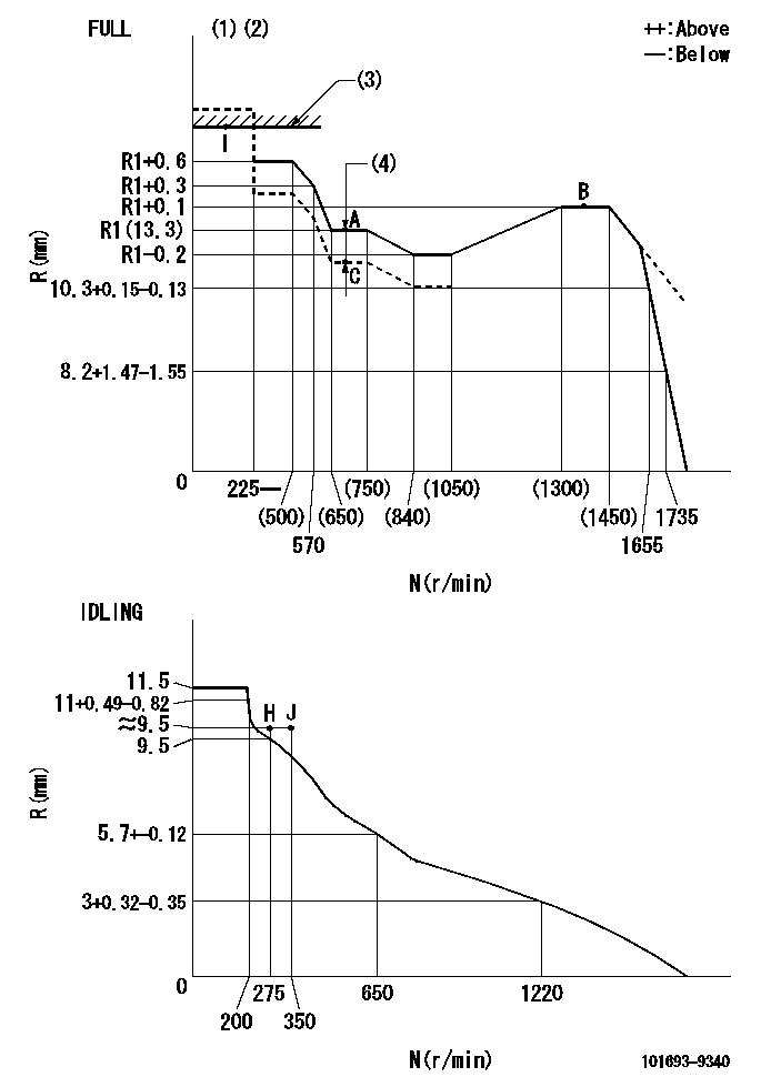
N:Pump speed
R:Rack position (mm)
(1)Torque cam stamping: T1
(2)Tolerance for racks not indicated: +-0.05mm.
(3)RACK LIMIT
(4)Boost compensator stroke: BCL
----------
T1=E91 BCL=2+-0.1mm
----------
----------
T1=E91 BCL=2+-0.1mm
----------
Timer adjustment
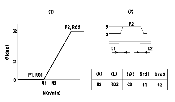
(1)Adjusting range
(2)Step response time
(N): Speed of the pump
(L): Load
(theta) Advance angle
(Srd1) Step response time 1
(Srd2) Step response time 2
1. Adjusting conditions for the variable timer
(1)Adjust the clearance between the pickup and the protrusion to L.
----------
L=1.5+-0.2mm N3=800r/min C3=(6.5deg) t1=2--sec. t2=2--sec.
----------
N1=1200++r/min N2=1400r/min P1=0kPa(0kgf/cm2) P2=392kPa(4kgf/cm2) C1=2.5--deg C2=6.5+-0.4deg R01=0/4load R02=4/4load
----------
L=1.5+-0.2mm N3=800r/min C3=(6.5deg) t1=2--sec. t2=2--sec.
----------
N1=1200++r/min N2=1400r/min P1=0kPa(0kgf/cm2) P2=392kPa(4kgf/cm2) C1=2.5--deg C2=6.5+-0.4deg R01=0/4load R02=4/4load
Speed control lever angle

F:Full speed
I:Idle
(1)R = aa
(2)Stopper bolt set position 'H'
----------
aa=36mm
----------
a=26.5deg+-5deg b=44deg+-3deg
----------
aa=36mm
----------
a=26.5deg+-5deg b=44deg+-3deg
Stop lever angle

N:Pump normal
S:Stop the pump.
----------
----------
a=20deg+-5deg b=40deg+-5deg
----------
----------
a=20deg+-5deg b=40deg+-5deg
0000001501 RACK SENSOR
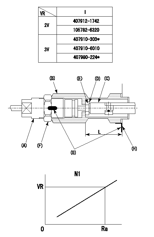
(VR) measurement voltage
(I) Part number of the control unit
(G) Apply red paint.
(H): End surface of the pump
1. Rack limit adjustment
(1)Fix the rack at the rack limit position Ra.
(2)Install the shim (D) to the rod (C) and tighten nut (E).
(3)Select a shim (D) so that the distance between the end surface of the pump and the nut (E) is L.
(4)Release the rack fixing and mount the joint (B) and fix.
(5)At this time, confirm that the shim (D) does not interfere with the joint (B).
2. Rack sensor adjustment (-0420)
(1)Screw in the bobbin (A) until it contacts the joint (B).
(2)Fix the speed control lever at the full side.
(3)Set the speed to N1 r/min.
(4)Adjust the depth that the bobbin (A) is screwed in so that the control unit's rack sensor output voltage is VR+-0.01 (V), then tighten the nut (F).
(5)Adjust the bobbin (A) so that the rack sensor's output voltage is VR.
(6)Apply G at two places.
Connecting part between the joint (B) and the nut (F)
Connecting part between the joint (B) and the end surface of the pump (H)
----------
L=33-0.2mm N1=700r/min Ra=R1(13.3)mm
----------
----------
L=33-0.2mm N1=700r/min Ra=R1(13.3)mm
----------
Timing setting

(1)Pump vertical direction
(2)Position of timer's threaded hole at No 1 cylinder's beginning of injection
(3)-
(4)-
----------
----------
a=(60deg)
----------
----------
a=(60deg)
Information:
Diagnostic Code 52 ECM or Personality Module Fault
Conditions Which Generate This Code:
The Electronic Control Module (ECM) has detected a fault in the Personality Module (PM), the ECM itself or the connector between them.System Response:
Diagnostic Code 52 is current (Diagnostic Lamp, ECAP or DDT) and is LOGGED in memory.Troubleshooting:
Refer to P-220: ECM And Personality Module Test.Diagnostic Code 53 ECM Fault
Conditions Which Generate This Code:
The ECM has detected an internal fault.System Response:
Diagnostic Code 53 is current (Diagnostic Lamp, ECAP, or DDT), and is LOGGED in memory.Troubleshooting:
The ECM must be replaced.Diagnostic Code 55 No Detected Faults
Conditions Which Generate This Code:
There are no ACTIVE Diagnostic Codes in the 3176 System.System Response:
Normal engine operation.Troubleshooting:
Diagnostic Code 55 does NOT indicate a 3176 System fault. It only shows that the system is operating correctly. The ECAP will display a Code 55 if no faults are currently ACTIVE. The Diagnostic Lamp will also flash Code 55 (on demand) if no faults have occurred since power-up.Diagnostic Code 56 Check Customer Or System Parameters
Conditions Which Generate This Code:
One or more of the Customer Specified Parameters and/or System Configuration Parameters are not correctly programmed for the system. Diagnostic Code 56 will be generated if the Electronic Control Module (ECM) has been replaced and any of the parameters have not been programmed.System Response:
1. Diagnostic Code 56 is current (Diagnostic Lamp, ECAP, or DDT), but is NOT LOGGED in memory.2. Engine power may be limited and/or the ECM may limit engine speed to low idle, depending on the parameter causing the Code 56.Troubleshooting:
1. Using an ECAP, read the parameters that triggered the code, shown along with the Diagnostic Code 56 on the " Current Diagnostic Messages" screen.2. Reprogram the displayed parameter(s). Refer to "Programming 3176 Parameters" in Section 2 of this manual.Diagnostic Code 57 Parking Brake Switch Fault
Conditions Which Generate This Code:
1. The Parking Brake Switch indicates the parking brake is ON.-AND-2. Diagnostic Code 36 (Vehicle Speed Signal Out Of Range) is NOT ACTIVE.-AND-3. The ECM reads a vehicle speed greater than 10 mph for at least five seconds.System Response:
1. Diagnostic Code 57 is current (Diagnostic Lamp, ECAP, or DDT), and IS LOGGED in memory.-AND-2. The Idle Shutdown Timer is disabled.Troubleshooting:
Follow P-216: Parking Brake Switch Test, in this manual.Diagnostic Code 63 Low Fuel Pressure Warning
Conditions Which Generate This Code:
1. The engine has been running at least 20 seconds.-AND-2. Diagnostic Code 37 (Fuel Pressure Sensor Fault) is not ACTIVE.-AND-3. Fuel pressure falls below the minimum specified for a given rpm for at least two minutes. Refer to the Chart below for minimum fuel pressure vs. rpm.System Response:
1. Diagnostic Code 63 is current (Diagnostic Lamp, ECAP, or DDT) and is LOGGED in memory.Troubleshooting:
1. Diagnostic Code 63 does NOT indicate a 3176 System fault. It only gives warning that a low fuel pressure condition exists.2. Use the procedures in the "Fuel System Inspection" and "Fuel Transfer Pump" sections of the 3176 Systems Operation Testing And Adjusting Manual, Form SENR3909, to determine the cause of the low fuel pressure condition. Diagnostic Code 72 Cylinder 1
Conditions Which Generate This Code:
The Electronic Control Module (ECM) has detected a fault in the Personality Module (PM), the ECM itself or the connector between them.System Response:
Diagnostic Code 52 is current (Diagnostic Lamp, ECAP or DDT) and is LOGGED in memory.Troubleshooting:
Refer to P-220: ECM And Personality Module Test.Diagnostic Code 53 ECM Fault
Conditions Which Generate This Code:
The ECM has detected an internal fault.System Response:
Diagnostic Code 53 is current (Diagnostic Lamp, ECAP, or DDT), and is LOGGED in memory.Troubleshooting:
The ECM must be replaced.Diagnostic Code 55 No Detected Faults
Conditions Which Generate This Code:
There are no ACTIVE Diagnostic Codes in the 3176 System.System Response:
Normal engine operation.Troubleshooting:
Diagnostic Code 55 does NOT indicate a 3176 System fault. It only shows that the system is operating correctly. The ECAP will display a Code 55 if no faults are currently ACTIVE. The Diagnostic Lamp will also flash Code 55 (on demand) if no faults have occurred since power-up.Diagnostic Code 56 Check Customer Or System Parameters
Conditions Which Generate This Code:
One or more of the Customer Specified Parameters and/or System Configuration Parameters are not correctly programmed for the system. Diagnostic Code 56 will be generated if the Electronic Control Module (ECM) has been replaced and any of the parameters have not been programmed.System Response:
1. Diagnostic Code 56 is current (Diagnostic Lamp, ECAP, or DDT), but is NOT LOGGED in memory.2. Engine power may be limited and/or the ECM may limit engine speed to low idle, depending on the parameter causing the Code 56.Troubleshooting:
1. Using an ECAP, read the parameters that triggered the code, shown along with the Diagnostic Code 56 on the " Current Diagnostic Messages" screen.2. Reprogram the displayed parameter(s). Refer to "Programming 3176 Parameters" in Section 2 of this manual.Diagnostic Code 57 Parking Brake Switch Fault
Conditions Which Generate This Code:
1. The Parking Brake Switch indicates the parking brake is ON.-AND-2. Diagnostic Code 36 (Vehicle Speed Signal Out Of Range) is NOT ACTIVE.-AND-3. The ECM reads a vehicle speed greater than 10 mph for at least five seconds.System Response:
1. Diagnostic Code 57 is current (Diagnostic Lamp, ECAP, or DDT), and IS LOGGED in memory.-AND-2. The Idle Shutdown Timer is disabled.Troubleshooting:
Follow P-216: Parking Brake Switch Test, in this manual.Diagnostic Code 63 Low Fuel Pressure Warning
Conditions Which Generate This Code:
1. The engine has been running at least 20 seconds.-AND-2. Diagnostic Code 37 (Fuel Pressure Sensor Fault) is not ACTIVE.-AND-3. Fuel pressure falls below the minimum specified for a given rpm for at least two minutes. Refer to the Chart below for minimum fuel pressure vs. rpm.System Response:
1. Diagnostic Code 63 is current (Diagnostic Lamp, ECAP, or DDT) and is LOGGED in memory.Troubleshooting:
1. Diagnostic Code 63 does NOT indicate a 3176 System fault. It only gives warning that a low fuel pressure condition exists.2. Use the procedures in the "Fuel System Inspection" and "Fuel Transfer Pump" sections of the 3176 Systems Operation Testing And Adjusting Manual, Form SENR3909, to determine the cause of the low fuel pressure condition. Diagnostic Code 72 Cylinder 1
Have questions with 101693-9340?
Group cross 101693-9340 ZEXEL
Nissan-Diesel
Nissan-Diesel
Nissan-Diesel
Nissan-Diesel
101693-9340
INJECTION-PUMP ASSEMBLY
