Information injection-pump assembly
ZEXEL
101693-9170
1016939170
NISSAN-DIESEL
16713Z5767
16713z5767
Rating:
Cross reference number
ZEXEL
101693-9170
1016939170
NISSAN-DIESEL
16713Z5767
16713z5767
Zexel num
Bosch num
Firm num
Name
101693-9170
16713Z5767 NISSAN-DIESEL
INJECTION-PUMP ASSEMBLY
FE6T * K
FE6T * K
Calibration Data:
Adjustment conditions
Test oil
1404 Test oil ISO4113 or {SAEJ967d}
1404 Test oil ISO4113 or {SAEJ967d}
Test oil temperature
degC
40
40
45
Nozzle and nozzle holder
105780-8140
Bosch type code
EF8511/9A
Nozzle
105780-0000
Bosch type code
DN12SD12T
Nozzle holder
105780-2080
Bosch type code
EF8511/9
Opening pressure
MPa
17.2
Opening pressure
kgf/cm2
175
Injection pipe
Outer diameter - inner diameter - length (mm) mm 6-2-600
Outer diameter - inner diameter - length (mm) mm 6-2-600
Overflow valve
132424-0620
Overflow valve opening pressure
kPa
157
123
191
Overflow valve opening pressure
kgf/cm2
1.6
1.25
1.95
Tester oil delivery pressure
kPa
157
157
157
Tester oil delivery pressure
kgf/cm2
1.6
1.6
1.6
Direction of rotation (viewed from drive side)
Right R
Right R
Injection timing adjustment
Direction of rotation (viewed from drive side)
Right R
Right R
Injection order
1-4-2-6-
3-5
Pre-stroke
mm
3.4
3.35
3.45
Beginning of injection position
Drive side NO.1
Drive side NO.1
Difference between angles 1
Cal 1-4 deg. 60 59.5 60.5
Cal 1-4 deg. 60 59.5 60.5
Difference between angles 2
Cyl.1-2 deg. 120 119.5 120.5
Cyl.1-2 deg. 120 119.5 120.5
Difference between angles 3
Cal 1-6 deg. 180 179.5 180.5
Cal 1-6 deg. 180 179.5 180.5
Difference between angles 4
Cal 1-3 deg. 240 239.5 240.5
Cal 1-3 deg. 240 239.5 240.5
Difference between angles 5
Cal 1-5 deg. 300 299.5 300.5
Cal 1-5 deg. 300 299.5 300.5
Injection quantity adjustment
Adjusting point
-
Rack position
14
Pump speed
r/min
550
550
550
Average injection quantity
mm3/st.
84.8
82.8
86.8
Max. variation between cylinders
%
0
-3.5
3.5
Basic
*
Fixing the rack
*
Standard for adjustment of the maximum variation between cylinders
*
Injection quantity adjustment_02
Adjusting point
-
Rack position
9.7+-0.5
Pump speed
r/min
275
275
275
Average injection quantity
mm3/st.
9.5
7.7
11.3
Max. variation between cylinders
%
0
-10
10
Fixing the rack
*
Standard for adjustment of the maximum variation between cylinders
*
Remarks
Adjust only variation between cylinders; adjust governor according to governor specifications.
Adjust only variation between cylinders; adjust governor according to governor specifications.
Injection quantity adjustment_03
Adjusting point
A
Rack position
R1(14)
Pump speed
r/min
550
550
550
Average injection quantity
mm3/st.
84.8
83.8
85.8
Basic
*
Fixing the lever
*
Boost pressure
kPa
25.3
25.3
Boost pressure
mmHg
190
190
Injection quantity adjustment_04
Adjusting point
B
Rack position
R1-0.1
Pump speed
r/min
850
850
850
Average injection quantity
mm3/st.
91.9
88.7
95.1
Fixing the lever
*
Boost pressure
kPa
25.3
25.3
Boost pressure
mmHg
190
190
Injection quantity adjustment_05
Adjusting point
C
Rack position
R1-0.3
Pump speed
r/min
1400
1400
1400
Average injection quantity
mm3/st.
96.5
93.3
99.7
Fixing the lever
*
Boost pressure
kPa
25.3
25.3
Boost pressure
mmHg
190
190
Injection quantity adjustment_06
Adjusting point
D
Rack position
R2(12.3)
Pump speed
r/min
550
550
550
Average injection quantity
mm3/st.
59.7
58.7
60.7
Fixing the lever
*
Boost pressure
kPa
0
0
0
Boost pressure
mmHg
0
0
0
Injection quantity adjustment_07
Adjusting point
I
Rack position
-
Pump speed
r/min
150
150
150
Average injection quantity
mm3/st.
83.5
83.5
103.5
Fixing the lever
*
Rack limit
*
Boost compensator adjustment
Pump speed
r/min
550
550
550
Rack position
R2(12.3)
Boost pressure
kPa
4
2.7
5.3
Boost pressure
mmHg
30
20
40
Boost compensator adjustment_02
Pump speed
r/min
550
550
550
Rack position
R1(14)
Boost pressure
kPa
12
12
12
Boost pressure
mmHg
90
90
90
Timer adjustment
Pump speed
r/min
1170--
Advance angle
deg.
0
0
0
Remarks
Start
Start
Timer adjustment_02
Pump speed
r/min
1120
Advance angle
deg.
0.5
Timer adjustment_03
Pump speed
r/min
1400
Advance angle
deg.
2
1.5
2.5
Remarks
Finish
Finish
Test data Ex:
Governor adjustment
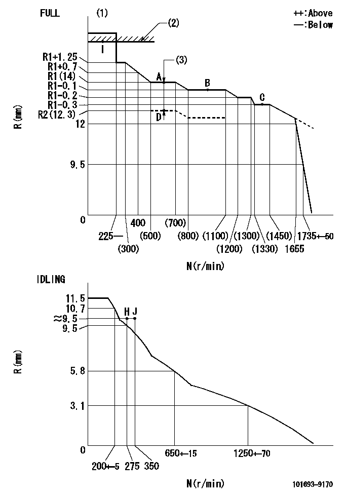
N:Pump speed
R:Rack position (mm)
(1)Torque cam stamping: T1
(2)RACK LIMIT
(3)Boost compensator stroke: BCL
----------
T1=C44 BCL=(1.7)+-0.1mm
----------
----------
T1=C44 BCL=(1.7)+-0.1mm
----------
Speed control lever angle

F:Full speed
I:Idle
(1)R = aa
(2)Stopper bolt set position 'H'
----------
aa=36mm
----------
a=26.5deg+-5deg b=(44deg)+-3deg
----------
aa=36mm
----------
a=26.5deg+-5deg b=(44deg)+-3deg
Stop lever angle
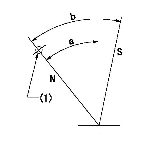
N:Pump normal
S:Stop the pump.
(1)Use the pin at R = aa
----------
aa=28mm
----------
a=37deg+-5deg b=40deg+-5deg
----------
aa=28mm
----------
a=37deg+-5deg b=40deg+-5deg
Timing setting

(1)Pump vertical direction
(2)Position of timer's threaded hole at No 1 cylinder's beginning of injection
(3)-
(4)-
----------
----------
a=(60deg)
----------
----------
a=(60deg)
Information:
Start By:a. remove valve covers 1. Remove bolts (1) that hold the valve cover bases to the cylinder head assembly. Remove valve cover bases (2). 2. Use tool (A) to loosen fuel injection line (3) from fuel injection nozzle (4). 3. Use tool (B) to loosen the nut at the fuel injection line adapter end. Remove inner fuel injection lines (3). Install caps and plugs on all fuel injection line openings to keep dirt out of the fuel system. 4. Remove bolts (5) that hold the rocker shaft assemblies to the cylinder head assembly.5. Remove rocker shaft assemblies (6). 6. Put identification marks on the push rods as to their location in the engine. Remove push rods (7). 7. Put identification marks on the bridges as to their location in the engine. Remove bridges (8) from the dowels on the cylinder head assembly.Install Rocker Shaft Assemblies And Push Rods
1. Put clean engine oil on the bridges and dowels. Install the original bridges in their respective locations. New bridges can be mixed.2. Install bridges (8) on the bridge dowels. While firmly pressing 0.5 to 4.5 kg (1 to 10 lb.) straight down on the top contact surface of the bridge, turn the adjusting screw clockwise until contact is made with the valve stem. Turn the screw an additional 20° to 30° (1/3 to 1/2 of 1 hex on nut). This will straighten the dowel in the guide and compensate for the slack in the threads. Hold the adjusting screw in this position, and tighten the locknut to a torque of 30 4 N m (22 3 lb.ft.). Install original push rods in their respective locations in the engine. New push rods can be mixed.3. Install push rods (7). 4. Put rocker shaft assemblies (6) in position on the cylinder head assembly.5. Put clean engine oil on the threads of bolts (5) that hold the shaft assemblies in place. Tighten the bolts first to a torque of 270 25 N m (200 18 lb.ft.). Start with the bolt in the center of the rocker shaft assembly. Tighten the bolts again to a torque of 450 20 N m (330 15 lb.ft.). Tighten the bolts again by hand to a torque of 450 20 N m (330 15 lb.ft.).
Do no cause damage to the O-ring seals on the inner fuel lines.
6. Install inner fuel injection lines (3). Tighten the fuel injection line adapter nuts (9) to a torque of 40 7 N m (30 5 lb.ft.) with tool (B).7. Tighten fuel injection line nut (10) to a torque of 40 7 N m (30 5 lb.ft.) with tool (A).8. Make adjustments to the valves until the intake valve clearance is 0.38 mm (.015 in.) and the exhaust valve clearance is 0.76 mm (.030 in.). See Valve Clearance Setting in Testing And Adjusting. Tighten the locknut to a torque of 30 4 N m (22 3 lb.ft.) and
Have questions with 101693-9170?
Group cross 101693-9170 ZEXEL
Nissan-Diesel
Nissan-Diesel
Nissan-Diesel
101693-9170
16713Z5767
INJECTION-PUMP ASSEMBLY
FE6T
FE6T