Information injection-pump assembly
ZEXEL
101693-9120
1016939120
NISSAN-DIESEL
1671395112
1671395112
Rating:
Cross reference number
ZEXEL
101693-9120
1016939120
NISSAN-DIESEL
1671395112
1671395112
Zexel num
Bosch num
Firm num
Name
101693-9120
1671395112 NISSAN-DIESEL
INJECTION-PUMP ASSEMBLY
ND6 * K
ND6 * K
Calibration Data:
Adjustment conditions
Test oil
1404 Test oil ISO4113 or {SAEJ967d}
1404 Test oil ISO4113 or {SAEJ967d}
Test oil temperature
degC
40
40
45
Nozzle and nozzle holder
105780-8140
Bosch type code
EF8511/9A
Nozzle
105780-0000
Bosch type code
DN12SD12T
Nozzle holder
105780-2080
Bosch type code
EF8511/9
Opening pressure
MPa
17.2
Opening pressure
kgf/cm2
175
Injection pipe
Outer diameter - inner diameter - length (mm) mm 6-2-600
Outer diameter - inner diameter - length (mm) mm 6-2-600
Overflow valve
132424-0620
Overflow valve opening pressure
kPa
157
123
191
Overflow valve opening pressure
kgf/cm2
1.6
1.25
1.95
Tester oil delivery pressure
kPa
157
157
157
Tester oil delivery pressure
kgf/cm2
1.6
1.6
1.6
Direction of rotation (viewed from drive side)
Right R
Right R
Injection timing adjustment
Direction of rotation (viewed from drive side)
Right R
Right R
Injection order
1-4-2-6-
3-5
Pre-stroke
mm
2.75
2.7
2.8
Beginning of injection position
Drive side NO.1
Drive side NO.1
Difference between angles 1
Cal 1-4 deg. 60 59.5 60.5
Cal 1-4 deg. 60 59.5 60.5
Difference between angles 2
Cyl.1-2 deg. 120 119.5 120.5
Cyl.1-2 deg. 120 119.5 120.5
Difference between angles 3
Cal 1-6 deg. 180 179.5 180.5
Cal 1-6 deg. 180 179.5 180.5
Difference between angles 4
Cal 1-3 deg. 240 239.5 240.5
Cal 1-3 deg. 240 239.5 240.5
Difference between angles 5
Cal 1-5 deg. 300 299.5 300.5
Cal 1-5 deg. 300 299.5 300.5
Injection quantity adjustment
Adjusting point
A
Rack position
9
Pump speed
r/min
800
800
800
Average injection quantity
mm3/st.
53.8
52.8
54.8
Max. variation between cylinders
%
0
-2
2
Basic
*
Fixing the lever
*
Injection quantity adjustment_02
Adjusting point
B
Rack position
8.7
Pump speed
r/min
1500
1500
1500
Average injection quantity
mm3/st.
66.1
64.1
68.1
Max. variation between cylinders
%
0
-4
4
Fixing the lever
*
Injection quantity adjustment_03
Adjusting point
-
Rack position
7.6+-0.5
Pump speed
r/min
225
225
225
Average injection quantity
mm3/st.
9
7.8
10.2
Max. variation between cylinders
%
0
-13
13
Fixing the rack
*
Remarks
Adjust only variation between cylinders; adjust governor according to governor specifications.
Adjust only variation between cylinders; adjust governor according to governor specifications.
Injection quantity adjustment_04
Adjusting point
D
Rack position
12.6+-0.
5
Pump speed
r/min
150
150
150
Average injection quantity
mm3/st.
84
84
Fixing the lever
*
Remarks
After startup boost setting
After startup boost setting
Timer adjustment
Pump speed
r/min
550--
Advance angle
deg.
0
0
0
Remarks
Start
Start
Timer adjustment_02
Pump speed
r/min
500
Advance angle
deg.
0.5
Timer adjustment_03
Pump speed
r/min
800
Advance angle
deg.
1.5
1
2
Timer adjustment_04
Pump speed
r/min
1200
Advance angle
deg.
4
3.5
4.5
Remarks
Finish
Finish
Test data Ex:
Governor adjustment
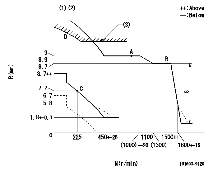
N:Pump speed
R:Rack position (mm)
(1)Damper spring setting: DL
(2)Set the load lever's stop position so that R = aa (N = 0).
(3)Excess fuel setting for starting: SXL
----------
DL=5.8-0.2mm aa=6.7mm SXL=10.9+0.2mm
----------
----------
DL=5.8-0.2mm aa=6.7mm SXL=10.9+0.2mm
----------
Speed control lever angle

F:Full speed
----------
----------
a=13deg+-5deg
----------
----------
a=13deg+-5deg
0000000901
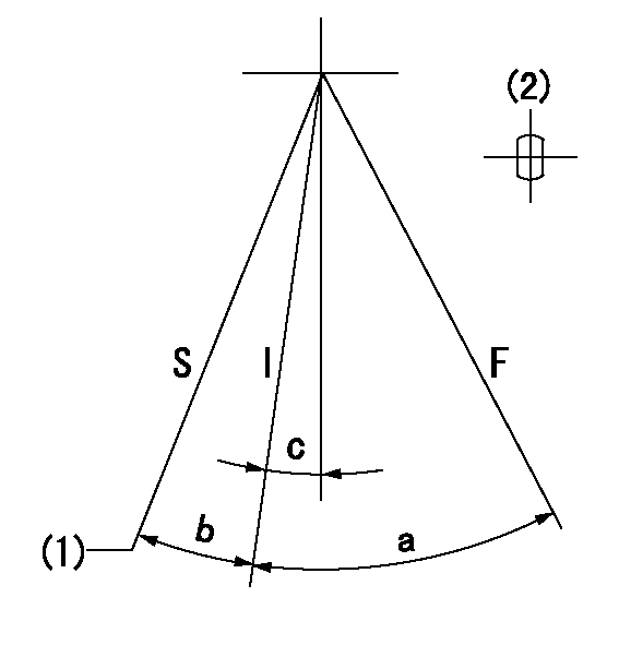
F:Full load
I:Idle
S:Stop
(1)Rack position aa (pump speed bb r/min )
(2)Lever shaft standard
----------
aa=6.7mm bb=0r/min
----------
a=27deg+-3deg b=(14deg)+-3deg c=9.5deg+-5deg
----------
aa=6.7mm bb=0r/min
----------
a=27deg+-3deg b=(14deg)+-3deg c=9.5deg+-5deg
Stop lever angle
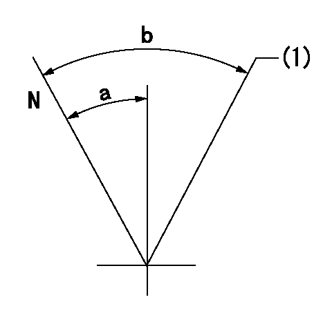
N:Pump normal
(1)Rack position = aa
----------
aa=7.2-0.2mm
----------
a=24deg+-5deg b=(48deg)+-5deg
----------
aa=7.2-0.2mm
----------
a=24deg+-5deg b=(48deg)+-5deg
Timing setting

(1)Pump vertical direction
(2)Coupling's key groove position at No 1 cylinder's beginning of injection
(3)-
(4)-
----------
----------
a=(40deg)
----------
----------
a=(40deg)
Information:
Start By:a remove rack actuator packageb. remove fuel injection pumps 1. Remove rack (1) from the fuel pump housing. 2. Remove six lifters (2) from the fuel pump housing. Put identification marks on the lifters for installation purposes. 3. Remove camshaft (3) from the fuel pump housing. It may be necessary to use a soft hammer to push the camshaft out of the governor end of the fuel pump housing. 4. Remove races (4) and bearing (5) from the camshaft. Remove ring (6) if necessary. 5. Remove rack bearing (7) from both ends of the housing and dowel (8) if necessary. 6. Use tooling (A), and remove three camshaft bearings (9). 7. Remove the bolts, cover (10) and the gasket. 8. Remove pins (12), the seal and dowels (11) if necessary. Pins (12) must be pushed from the inside out.Assemble Fuel Injection Pump Housing
1. Clean and inspect all parts. Make a replacement of all parts that are worn or damaged. 2. Lubricate the seal with clean engine oil, and install pin (12). Pin (12) must protrude into the pump bore 2.15 .05 mm (0.85 .002 in.).3. Install dowel (11) so that it protrudes into the pump bore 1.93 .05 mm (0.76 .002 in.). 4. Install the gasket, cover (10) and the bolts. 5. Install the rack bearing with tooling (B). Install the bearing until the driver comes in contact with the plate. The bearing should be installed to a depth of 83.0 0.5 mm (3.27 .02 in.) from the fuel pump mounting face. 6. Measure the rack bearing (7). Dimension (X) must be 11.178 0.05 mm (.4400 .002 in.). Dimension (W) must be 12.767 0.058 mm (.5026 .0022 in.). 7. Install dowel (8). Dowel (8) must protrude 6.0 0.5 mm (.24 .02 in.) from the fuel pump housing face.8. Install the rear rack bearing with tooling (C) to a depth of 7.16 0.13 mm (.282 .005 in.) below the fuel pump housing surface. The inside diameter of the rear rack bearing must be 12.746 0.045 mm (.5018 .0017 in.). 9. User tooling (D), and install three camshaft bearings (9). Oil holes (13) in the camshaft bearings must be positioned 30° 3° above the horizontal centerline toward the engine side of the fuel pump housing. The outer bearings must be installed 1.0 0.5 mm (0.04 0.02 in.) below the surface marked (Z). The inner bearing must be installed 218.0 0.3 mm (8.58 .012 in.) below the front surface (Y). Diameter (XX) must be 68.339 0.038 mm (2.6905 0.015 in.) after assembly. 10. Install ring (6) races (4) and bearing (5) on the camshaft. 11. Lubricate can bearings (9) and cam shaft bearing journals with clean engine oil.12. Install camshaft (3) into the fuel pump housing.
The notch on the lifter must be in line with the dowel in the lifter bore. The lifter must slide up and
Have questions with 101693-9120?
Group cross 101693-9120 ZEXEL
Nissan-Diesel
Nissan-Diesel
101693-9120
1671395112
INJECTION-PUMP ASSEMBLY
ND6
ND6