Information injection-pump assembly
ZEXEL
101693-9110
1016939110
NISSAN-DIESEL
1670095074
1670095074
Rating:
Cross reference number
ZEXEL
101693-9110
1016939110
NISSAN-DIESEL
1670095074
1670095074
Zexel num
Bosch num
Firm num
Name
101693-9110
1670095074 NISSAN-DIESEL
INJECTION-PUMP ASSEMBLY
ND6 * K
ND6 * K
Calibration Data:
Adjustment conditions
Test oil
1404 Test oil ISO4113 or {SAEJ967d}
1404 Test oil ISO4113 or {SAEJ967d}
Test oil temperature
degC
40
40
45
Nozzle and nozzle holder
105780-8140
Bosch type code
EF8511/9A
Nozzle
105780-0000
Bosch type code
DN12SD12T
Nozzle holder
105780-2080
Bosch type code
EF8511/9
Opening pressure
MPa
17.2
Opening pressure
kgf/cm2
175
Injection pipe
Outer diameter - inner diameter - length (mm) mm 6-2-600
Outer diameter - inner diameter - length (mm) mm 6-2-600
Overflow valve
132424-0620
Overflow valve opening pressure
kPa
157
123
191
Overflow valve opening pressure
kgf/cm2
1.6
1.25
1.95
Tester oil delivery pressure
kPa
157
157
157
Tester oil delivery pressure
kgf/cm2
1.6
1.6
1.6
Direction of rotation (viewed from drive side)
Right R
Right R
Injection timing adjustment
Direction of rotation (viewed from drive side)
Right R
Right R
Injection order
1-4-2-6-
3-5
Pre-stroke
mm
2.75
2.7
2.8
Beginning of injection position
Drive side NO.1
Drive side NO.1
Difference between angles 1
Cal 1-4 deg. 60 59.5 60.5
Cal 1-4 deg. 60 59.5 60.5
Difference between angles 2
Cyl.1-2 deg. 120 119.5 120.5
Cyl.1-2 deg. 120 119.5 120.5
Difference between angles 3
Cal 1-6 deg. 180 179.5 180.5
Cal 1-6 deg. 180 179.5 180.5
Difference between angles 4
Cal 1-3 deg. 240 239.5 240.5
Cal 1-3 deg. 240 239.5 240.5
Difference between angles 5
Cal 1-5 deg. 300 299.5 300.5
Cal 1-5 deg. 300 299.5 300.5
Injection quantity adjustment
Adjusting point
A
Rack position
9
Pump speed
r/min
800
800
800
Average injection quantity
mm3/st.
53.8
52.8
54.8
Max. variation between cylinders
%
0
-2
2
Basic
*
Fixing the lever
*
Injection quantity adjustment_02
Adjusting point
B
Rack position
8.7
Pump speed
r/min
1500
1500
1500
Average injection quantity
mm3/st.
66.1
64.1
68.1
Max. variation between cylinders
%
0
-4
4
Fixing the lever
*
Injection quantity adjustment_03
Adjusting point
C
Rack position
7.6+-0.5
Pump speed
r/min
225
225
225
Average injection quantity
mm3/st.
9
7.8
10.2
Max. variation between cylinders
%
0
-13
13
Fixing the rack
*
Remarks
Adjust only variation between cylinders; adjust governor according to governor specifications.
Adjust only variation between cylinders; adjust governor according to governor specifications.
Injection quantity adjustment_04
Adjusting point
D
Rack position
12.6+-0.
5
Pump speed
r/min
150
150
150
Average injection quantity
mm3/st.
84
84
Fixing the lever
*
Remarks
After startup boost setting
After startup boost setting
Timer adjustment
Pump speed
r/min
550--
Advance angle
deg.
0
0
0
Remarks
Start
Start
Timer adjustment_02
Pump speed
r/min
500
Advance angle
deg.
0.5
Timer adjustment_03
Pump speed
r/min
800
Advance angle
deg.
1.5
1
2
Timer adjustment_04
Pump speed
r/min
1200
Advance angle
deg.
4
3.5
4.5
Remarks
Finish
Finish
Test data Ex:
Governor adjustment
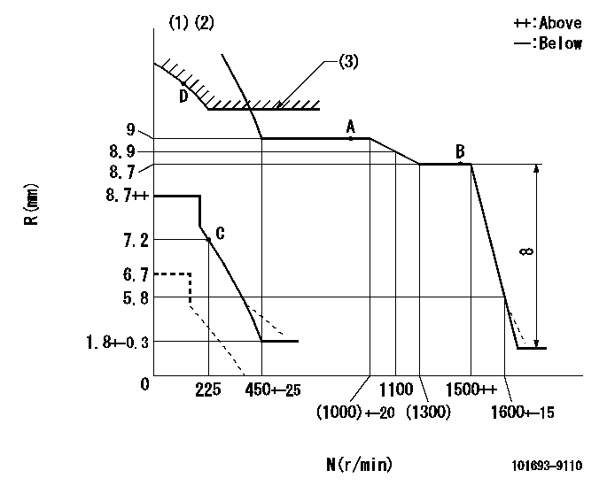
N:Pump speed
R:Rack position (mm)
(1)Damper spring setting: DL
(2)Set the load lever's stop position so that R = aa (N = 0).
(3)Excess fuel setting for starting: SXL
----------
DL=5.8-0.2mm aa=6.7mm SXL=10.9+0.2mm
----------
----------
DL=5.8-0.2mm aa=6.7mm SXL=10.9+0.2mm
----------
0000000901
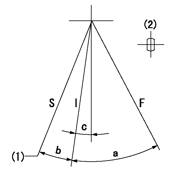
F:Full load
I:Idle
S:Stop
(1)Rack position aa (pump speed bb r/min )
(2)Lever shaft standard
----------
aa=6.7mm bb=0r/min
----------
a=27deg+-3deg b=(14deg)+-3deg c=9.5deg+-5deg
----------
aa=6.7mm bb=0r/min
----------
a=27deg+-3deg b=(14deg)+-3deg c=9.5deg+-5deg
Stop lever angle
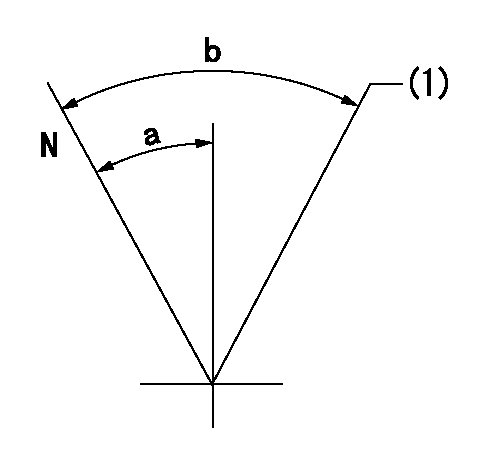
N:Pump normal
(1)Rack position = aa
----------
aa=7.2-0.2mm
----------
a=24deg+-5deg b=(48deg)+-5deg
----------
aa=7.2-0.2mm
----------
a=24deg+-5deg b=(48deg)+-5deg
Timing setting

(1)Pump vertical direction
(2)Coupling's key groove position at No 1 cylinder's beginning of injection
(3)-
(4)-
----------
----------
a=(40deg)
----------
----------
a=(40deg)
Information:
Start By:a. remove fuel injection linesb. remove rack actuator package 1. Remove the plug, and move the rack until tool (A) can be installed to hold the rack in the center position. The rack must be in the center position to remove the fuel injection pumps.
To prevent possible personal injury carefully follow the steps below.
2. Put tooling (B), except for the 8S4613 Wrench, in position on the fuel pump housing as shown. Lower the handle to center the adjusting screw with the fuel line seat. With the handle down in the locked position, the adjusting screw must just be in contact with fuel line seat (1). If force is needed to lower the handle or there is a gap, remove the tooling, and make an adjustment to the screw.3. Loosen bushing (2) 1/4 of a turn.4. Put tooling (B) in position on the pump housing with the handle down in the locked position as shown.5. Remove bushing (2) from the pump housing.6. Carefully and slowly lift the handle to release the spring force. Remove the tooling. 7. Install tool (C) on fuel pump (4) as shown.8. Remove seal (3) and fuel pump (4) from the fuel pump housing. 9. Remove spacers (5) from the pump housing. There must be a pump installed on either side of the pump to be removed to install tooling (B). If there is no pump, take a pump already removed, and remove the spring so there will be no spring force, and install it in the pump housing. See Install Fuel Pump. Spacers (5) are the same thickness for each fuel injection pump so they can be mixed. The fuel injection pump plungers and barrels are sets and cannot be mixed.Install Fuel Injection Pumps
1. Install spacers (5) in the fuel pump housing.2. Move the rack until tool (A) can be installed to hold the rack in the center position. The rack must be in the center position to install the fuel injection pumps.3. Install a fuel pump without its spring so that tool (B) can be installed. See Step 5 for correct fuel pump installation. 4. Install tool (C) on the bonnet of the fuel pump as shown.5. Install the fuel pump in the pump housing with the saw cut (slot) (9) in the gear in alignment with small pin (6) in the lifter assembly and groove (8) in the barrel in alignment with large pin (7) in the pump housing. 6. Install the seal and bushing (2) on the fuel pump.7. Put tooling (B) in position on the fuel pump housing as shown.8. Lower the handle slowly and carefully. If the fuel pump is not installed correctly, the handle will not go all the way down. Do not try to use force on it. Remove And Install the tooling and the fuel pump again.9. Make sure the seal is in the correct position, and start to tighten bushing (2). Remove the tooling, and tighten the bushing to a torque of 215
Have questions with 101693-9110?
Group cross 101693-9110 ZEXEL
Nissan-Diesel
Nissan-Diesel
101693-9110
1670095074
INJECTION-PUMP ASSEMBLY
ND6
ND6