Information injection-pump assembly
ZEXEL
101693-2740
1016932740
HINO
220801010B
220801010b
Rating:
Service parts 101693-2740 INJECTION-PUMP ASSEMBLY:
1.
_
5.
AUTOM. ADVANCE MECHANIS
7.
COUPLING PLATE
8.
_
9.
_
10.
NOZZLE AND HOLDER ASSY
11.
Nozzle and Holder
12.
Open Pre:MPa(Kqf/cm2)
13.
NOZZLE-HOLDER
15.
NOZZLE SET
Cross reference number
ZEXEL
101693-2740
1016932740
HINO
220801010B
220801010b
Zexel num
Bosch num
Firm num
Name
Calibration Data:
Adjustment conditions
Test oil
1404 Test oil ISO4113 or {SAEJ967d}
1404 Test oil ISO4113 or {SAEJ967d}
Test oil temperature
degC
40
40
45
Nozzle and nozzle holder
105780-8140
Bosch type code
EF8511/9A
Nozzle
105780-0000
Bosch type code
DN12SD12T
Nozzle holder
105780-2080
Bosch type code
EF8511/9
Opening pressure
MPa
17.2
Opening pressure
kgf/cm2
175
Injection pipe
Outer diameter - inner diameter - length (mm) mm 6-2-600
Outer diameter - inner diameter - length (mm) mm 6-2-600
Tester oil delivery pressure
kPa
157
157
157
Tester oil delivery pressure
kgf/cm2
1.6
1.6
1.6
Direction of rotation (viewed from drive side)
Right R
Right R
Injection timing adjustment
Direction of rotation (viewed from drive side)
Right R
Right R
Injection order
1-4-2-6-
3-5
Pre-stroke
mm
2.1
2.05
2.15
Rack position
After adjusting injection quantity. R=B
After adjusting injection quantity. R=B
Beginning of injection position
Drive side NO.1
Drive side NO.1
Difference between angles 1
Cal 1-4 deg. 60 59.5 60.5
Cal 1-4 deg. 60 59.5 60.5
Difference between angles 2
Cyl.1-2 deg. 120 119.5 120.5
Cyl.1-2 deg. 120 119.5 120.5
Difference between angles 3
Cal 1-6 deg. 180 179.5 180.5
Cal 1-6 deg. 180 179.5 180.5
Difference between angles 4
Cal 1-3 deg. 240 239.5 240.5
Cal 1-3 deg. 240 239.5 240.5
Difference between angles 5
Cal 1-5 deg. 300 299.5 300.5
Cal 1-5 deg. 300 299.5 300.5
Injection quantity adjustment
Adjusting point
A
Rack position
12.8
Pump speed
r/min
600
600
600
Average injection quantity
mm3/st.
106
106
106
Max. variation between cylinders
%
0
-4
4
Fixing the lever
*
Injection quantity adjustment_02
Adjusting point
B
Rack position
12.6
Pump speed
r/min
1175
1175
1175
Average injection quantity
mm3/st.
108.5
107.5
109.5
Max. variation between cylinders
%
0
-2
2
Basic
*
Fixing the lever
*
Injection quantity adjustment_03
Adjusting point
C
Rack position
7+-0.5
Pump speed
r/min
200
200
200
Average injection quantity
mm3/st.
16.5
13.9
19.1
Max. variation between cylinders
%
0
-13
13
Fixing the rack
*
Injection quantity adjustment_04
Adjusting point
D
Rack position
-
Pump speed
r/min
1000
1000
1000
Average injection quantity
mm3/st.
1
Fixing the lever
*
Timer adjustment
Pump speed
r/min
500+-50
Advance angle
deg.
0
0
0
Remarks
Start
Start
Timer adjustment_02
Pump speed
r/min
600
Advance angle
deg.
0.4
0.1
1.1
Timer adjustment_03
Pump speed
r/min
800
Advance angle
deg.
1.25
0.75
1.75
Timer adjustment_04
Pump speed
r/min
950
Advance angle
deg.
1.7
1.2
2.2
Timer adjustment_05
Pump speed
r/min
1150
Advance angle
deg.
2.5
2
3
Remarks
Finish
Finish
Test data Ex:
Governor adjustment
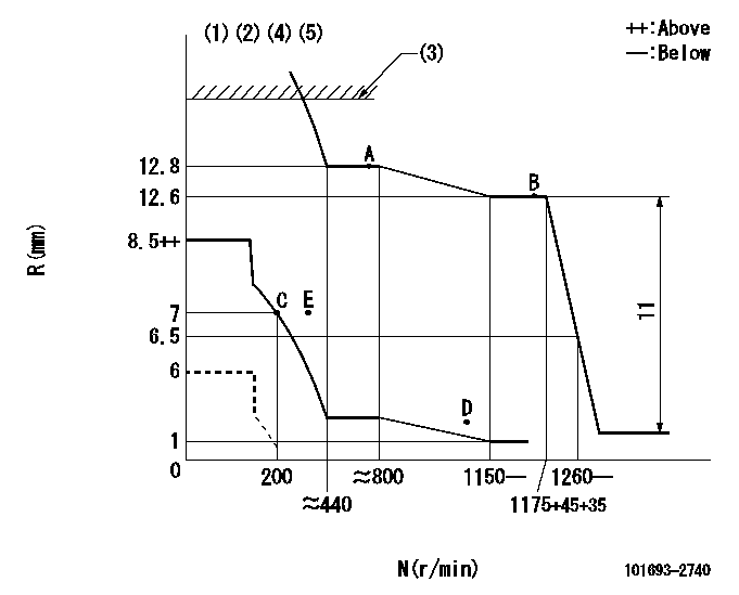
N:Pump speed
R:Rack position (mm)
(1)Minimum - maximum speed specification
(2)Beginning of damper spring operation: DL
(3)RACK LIMIT: RAL
(4)Set idle at point E (N = N1, R = R1) and confirm that the injection quantity at N = N2 is at point D or less.
(5)Set the load lever's stop position so that R = aa (N = 0).
----------
DL=6.5-0.2mm RAL=15+0.2mm N1=275r/min R1=7mm N2=1000r/min aa=6mm
----------
----------
DL=6.5-0.2mm RAL=15+0.2mm N1=275r/min R1=7mm N2=1000r/min aa=6mm
----------
Speed control lever angle
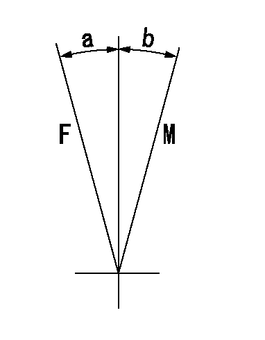
F:Full speed
M:Minimum-maximum speed
----------
----------
a=11deg+-5deg b=(18deg)
----------
----------
a=11deg+-5deg b=(18deg)
0000000901
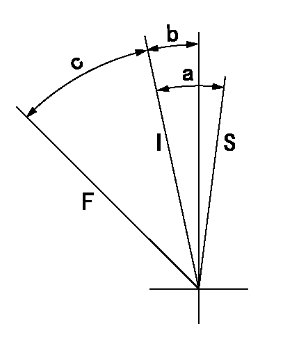
F:Full load
I:Idle
S:Stop
----------
----------
a=7.5deg+-5deg b=2.5deg+-5deg c=42deg+-3deg
----------
----------
a=7.5deg+-5deg b=2.5deg+-5deg c=42deg+-3deg
0000001501 MICRO SWITCH
Switch adjustment
Adjust the bolt so that the lower lever position is obtained when the switch is turned ON.
(1)Speed N1
(2)Rack position Ra
----------
N1=300r/min Ra=7mm
----------
----------
N1=300r/min Ra=7mm
----------
Information:
4. Install a new seal washer (6).Use 6V-4979 Carbon Stop Seal Tool (4) to install new carbon dam (5) on nozzle (2).7000 Series Nozzles
The part number for compression seal (3) is not the same for all nozzles. If the correct seal is not installed, the result will be high emissions. This is NOT acceptable.
Troubleshooting (Pencil-Type Fuel Nozzles Only)
A. To troubleshoot these nozzles, refer to the Troubleshooting Guide For Pencil-Type Fuel Nozzles located in this manual.B. Refer to Special Instruction SEHS8627 "Use of 8S-2245 Nozzle Cleaning Tool Group" for the correct procedure (according to the part number of the nozzle) in order to clean these nozzles. C. If VO is LESS than the specified value for a specific part number, DO NOT use the nozzle.Troubleshooting Guide For Pencil-Type Fuel Nozzles
Troubleshooting Guide For Caterpillar 7000 Series Direct Injection Fuel Nozzles
Engine Nozzle Test Record Form (Sample Copy)
Repair/Calibration Information For 5P-4150 Tester Group
For the repair and/or calibration of the 5P-4150 Tester Group, contact the manufacturer: U.S. Mail:OTC Division
SPX Corporation
655 Eisenhower Drive
Owatonna, Minnesota 55060, U.S.A.
Telephone:(507) 455-7000(800) 533-6127 Fax:(800) 955-8329Test Equipment Calibration
Caterpillar fuel nozzle and unit injector testers feature premium quality, liquid filled gauges for high accuracy and durability.Pressure gauges, in this application must be of high quality in order to provide accurate and consistent test results.To maintain this high degree of accuracy, gauge calibration should be checked at a MINIMUM of once a year. Additional information can be found in NEHS0631 "General Maintenance And Troubleshooting For Fuel Injection Equipment Test Stands (FIETS) And 5P-4150 Nozzle Tester". However, calibration should be checked at any time when the test results have become INCONSISTENT or if the gauge needle does NOT return to the 0 (zero) range when the test pressure is relieved.Calibration
Two methods are available for gauge calibration:* Method 1: Calibration by gauge manufacturer.* Method 2: 5P-8558 Pressure Gauge Calibrating Group. Additional information can be found in NEHS0631 "General Maintenance And Troubleshooting For Fuel Injection Equipment Test Stands (FIETS) And 5P-4150 Nozzle Tester".Calibration By Gauge Manufacturer (Method 1)
Certified calibration services are offered by Carrier - Oehler Company, a Caterpillar certified supplier of premium quality gauges.The Carrier - Oehler Company can promptly check and recalibrate gauges at a low cost.The Carrier - Oehler Company will also repair and recalibrate damaged gauges at a fraction of the cost of a new gauge.When sending gauges to Carrier - Oehler Company, include the following information:* Person or department that gauges and/or correspondence is to be directed to.* List the quantity and a brief description of the gauge(s) problem or the service requested.* Dealer name and address.* Telephone number.* Fax number. The Carrier - Oehler Company will advise you if repair costs exceed 50 percent of a new gauge. Questions on costs, service, and repair time should be directed to the Caterpillar Repair Desk:(800) 321-3241 Shipping:Carrier - Oehler Company
16965 Vincennes Avenue
South Holland, Illinois 60473
U.S. Mail:Carrier - Oehler Company
Post Office Box 40
16965 Vincennes Avenue
South Holland, Illinois 60473
Telephone:(708) 339-8200 Fax:(708) 339-98305P-8558 Pressure Gauge Calibrating Group (Method 2)
(1) 5P-0946 Box Assembly.(2) 1P-2375 Quick