Information injection-pump assembly
BOSCH
9 400 616 065
9400616065
ZEXEL
101692-9320
1016929320
NISSAN-DIESEL
16790Z5577
16790z5577
Rating:
Service parts 101692-9320 INJECTION-PUMP ASSEMBLY:
1.
_
5.
AUTOM. ADVANCE MECHANIS
7.
COUPLING PLATE
8.
_
9.
_
11.
Nozzle and Holder
16600-Z5519
12.
Open Pre:MPa(Kqf/cm2)
19.6{200}

15.
NOZZLE SET
Cross reference number
BOSCH
9 400 616 065
9400616065
ZEXEL
101692-9320
1016929320
NISSAN-DIESEL
16790Z5577
16790z5577
Zexel num
Bosch num
Firm num
Name
101692-9320
9 400 616 065
16790Z5577 NISSAN-DIESEL
INJECTION-PUMP ASSEMBLY
FE6T04 K 14BE INJECTION PUMP ASSY PE6A PE
FE6T04 K 14BE INJECTION PUMP ASSY PE6A PE
Calibration Data:
Adjustment conditions
Test oil
1404 Test oil ISO4113 or {SAEJ967d}
1404 Test oil ISO4113 or {SAEJ967d}
Test oil temperature
degC
40
40
45
Nozzle and nozzle holder
105780-8140
Bosch type code
EF8511/9A
Nozzle
105780-0000
Bosch type code
DN12SD12T
Nozzle holder
105780-2080
Bosch type code
EF8511/9
Opening pressure
MPa
17.2
Opening pressure
kgf/cm2
175
Injection pipe
Outer diameter - inner diameter - length (mm) mm 6-2-600
Outer diameter - inner diameter - length (mm) mm 6-2-600
Overflow valve opening pressure
kPa
157
123
191
Overflow valve opening pressure
kgf/cm2
1.6
1.25
1.95
Tester oil delivery pressure
kPa
157
157
157
Tester oil delivery pressure
kgf/cm2
1.6
1.6
1.6
Direction of rotation (viewed from drive side)
Right R
Right R
Injection timing adjustment
Direction of rotation (viewed from drive side)
Right R
Right R
Injection order
1-4-2-6-
3-5
Pre-stroke
mm
3.4
3.35
3.45
Beginning of injection position
Drive side NO.1
Drive side NO.1
Difference between angles 1
Cal 1-4 deg. 60 59.5 60.5
Cal 1-4 deg. 60 59.5 60.5
Difference between angles 2
Cyl.1-2 deg. 120 119.5 120.5
Cyl.1-2 deg. 120 119.5 120.5
Difference between angles 3
Cal 1-6 deg. 180 179.5 180.5
Cal 1-6 deg. 180 179.5 180.5
Difference between angles 4
Cal 1-3 deg. 240 239.5 240.5
Cal 1-3 deg. 240 239.5 240.5
Difference between angles 5
Cal 1-5 deg. 300 299.5 300.5
Cal 1-5 deg. 300 299.5 300.5
Injection quantity adjustment
Adjusting point
A
Rack position
14.1
Pump speed
r/min
750
750
750
Average injection quantity
mm3/st.
91
89.5
92.5
Max. variation between cylinders
%
0
-3.5
3.5
Basic
*
Fixing the lever
*
Injection quantity adjustment_02
Adjusting point
C
Rack position
9.5+-0.5
Pump speed
r/min
300
300
300
Average injection quantity
mm3/st.
8
6.2
9.8
Max. variation between cylinders
%
0
-10
10
Fixing the rack
*
Test data Ex:
Governor adjustment
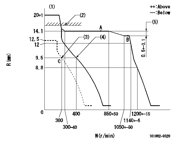
N:Pump speed
R:Rack position (mm)
(1)Target notch: K
(2)RACK LIMIT: RAL
(3)Set idle sub-spring
(4)Main spring setting
(5)Rack difference between N = N1 and N = N2
----------
K=15 RAL=14.6+-0.1mm N1=1100r/min N2=750r/min
----------
----------
K=15 RAL=14.6+-0.1mm N1=1100r/min N2=750r/min
----------
Speed control lever angle

F:Full speed
I:Idle
(1)Stopper bolt setting
----------
----------
a=7deg+-5deg b=22deg+-5deg
----------
----------
a=7deg+-5deg b=22deg+-5deg
Stop lever angle

N:Pump normal
S:Stop the pump.
----------
----------
a=26.5deg+-5deg b=53deg+-5deg
----------
----------
a=26.5deg+-5deg b=53deg+-5deg
Timing setting

(1)Pump vertical direction
(2)Position of coupling's threaded hole at No 1 cylinder's beginning of injection
(3)-
(4)-
----------
----------
a=(60deg)
----------
----------
a=(60deg)
Information:
Oil pressure should raise within nine seconds after the engine starts. If no oil pressure is indicated within ten seconds, the engine will shutdown. Investigate and correct the cause.
7. Do not apply load to the engine or increase engine rpm until the operating parameter readings indicate normal. Check all GSC display window readings during the warm-up period. Engine Starting Sequence
1. The GSC receives an engine start signal. The possible engine start signals are: a. ECS (Engine Control Switch) turned to MAN. START by the operatorb. The remote initiate contacts (IC) close while the ECS is in the AUTO position.2. The GSC checks the system before beginning the cranking sequence. The GSC checks that: a. No system faults are present.b. All previous faults have been reset (removed by turning the ECS to OFF/RESET).c. The engine is not already running.d. The service mode is not activated.3. The GSC activates the starting motor relay (SMR) and the run relay (RR).4. The GSC activates the fuel control relay (FCR) for the ETR fuel systems.5. The GSC cycle cranks (factory default is ten seconds crank and ten seconds rest) the engine until it starts or until the cycle crank time reaches the setpoint for total cycle crank time (overcrank).6. While the starting motor is cranking, the GSC shows the status of the relays on the relay status indicators of the lower display (i.e. K4, K5, K7 for ETR fuel systems).7. The GSC deactivates the starting motor relay (SMR) and activates the crank termination relay (CTR) when the engine speed reaches the setpoint for crank terminate speed (factory default is 400 rpm).8. The GSC activates the electronic governor (EG) relay when the oil pressure reaches the setpoint for low oil pressure at idle speed (factory default is 69 kPa [10 psi]). The EG relay signals the electronic governor (EG) to accelerate the engine to rated speed.9. The GSC shows: a. AC voltage, current, and frequency for one phase at a time on the upper display.b. System battery voltage, engine hours, engine rpm, oil pressure, and coolant temperature on the lower display.c. The relay status on the relay status indicators of the lower display. K1, K3, K5, K7 for ETR fuel systems.Starting From External Electrical Source
Make initial determination as to failure of engine to crank. Refer to special instruction SEHS7768 on use of 6V2150 Starting/Charging Analyzer Group.If the installation is not equipped with a back-up battery system, then it may be necessary to start the engine from an external electrical source. Many batteries thought to be unusable, are still rechargeable. Severely discharged maintenance free batteries might not fully recharge from the alternator alone after jump starting. The batteries must be charged to the proper voltage with a battery charger. Refer to Special Instruction, SEHS7633, Battery Test Procedure, available from your Caterpillar dealer, for complete testing and charging information.
Before attaching the booster cables, move ECS switch to OFF/RESET. Be sure the main power switch is in the OFF position before attaching the booster cables to
Have questions with 101692-9320?
Group cross 101692-9320 ZEXEL
Nissan-Diesel
101692-9320
9 400 616 065
16790Z5577
INJECTION-PUMP ASSEMBLY
FE6T04
FE6T04