Information injection-pump assembly
BOSCH
9 400 616 064
9400616064
ZEXEL
101692-9310
1016929310
NISSAN-DIESEL
16712Z5509
16712z5509
Rating:
Service parts 101692-9310 INJECTION-PUMP ASSEMBLY:
1.
_
5.
AUTOM. ADVANCE MECHANIS
7.
COUPLING PLATE
8.
_
9.
_
11.
Nozzle and Holder
16600-Z5519
12.
Open Pre:MPa(Kqf/cm2)
19.6{200}

15.
NOZZLE SET
Cross reference number
BOSCH
9 400 616 064
9400616064
ZEXEL
101692-9310
1016929310
NISSAN-DIESEL
16712Z5509
16712z5509
Zexel num
Bosch num
Firm num
Name
101692-9310
9 400 616 064
16712Z5509 NISSAN-DIESEL
INJECTION-PUMP ASSEMBLY
FE6T05 K 14BE INJECTION PUMP ASSY PE6A PE
FE6T05 K 14BE INJECTION PUMP ASSY PE6A PE
Calibration Data:
Adjustment conditions
Test oil
1404 Test oil ISO4113 or {SAEJ967d}
1404 Test oil ISO4113 or {SAEJ967d}
Test oil temperature
degC
40
40
45
Nozzle and nozzle holder
105780-8140
Bosch type code
EF8511/9A
Nozzle
105780-0000
Bosch type code
DN12SD12T
Nozzle holder
105780-2080
Bosch type code
EF8511/9
Opening pressure
MPa
17.2
Opening pressure
kgf/cm2
175
Injection pipe
Outer diameter - inner diameter - length (mm) mm 6-2-600
Outer diameter - inner diameter - length (mm) mm 6-2-600
Overflow valve
132424-0620
Overflow valve opening pressure
kPa
157
123
191
Overflow valve opening pressure
kgf/cm2
1.6
1.25
1.95
Tester oil delivery pressure
kPa
157
157
157
Tester oil delivery pressure
kgf/cm2
1.6
1.6
1.6
Direction of rotation (viewed from drive side)
Right R
Right R
Injection timing adjustment
Direction of rotation (viewed from drive side)
Right R
Right R
Injection order
1-4-2-6-
3-5
Pre-stroke
mm
3.4
3.35
3.45
Beginning of injection position
Drive side NO.1
Drive side NO.1
Difference between angles 1
Cal 1-4 deg. 60 59.5 60.5
Cal 1-4 deg. 60 59.5 60.5
Difference between angles 2
Cyl.1-2 deg. 120 119.5 120.5
Cyl.1-2 deg. 120 119.5 120.5
Difference between angles 3
Cal 1-6 deg. 180 179.5 180.5
Cal 1-6 deg. 180 179.5 180.5
Difference between angles 4
Cal 1-3 deg. 240 239.5 240.5
Cal 1-3 deg. 240 239.5 240.5
Difference between angles 5
Cal 1-5 deg. 300 299.5 300.5
Cal 1-5 deg. 300 299.5 300.5
Injection quantity adjustment
Adjusting point
A
Rack position
13.3
Pump speed
r/min
750
750
750
Average injection quantity
mm3/st.
81.6
79.6
83.6
Max. variation between cylinders
%
0
-2
2
Basic
*
Fixing the rack
*
Injection quantity adjustment_02
Adjusting point
C
Rack position
9.5+-0.5
Pump speed
r/min
300
300
300
Average injection quantity
mm3/st.
8
6.2
9.8
Max. variation between cylinders
%
0
-12
12
Fixing the rack
*
Test data Ex:
Governor adjustment
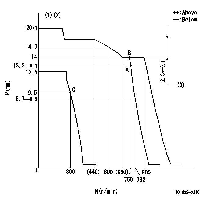
N:Pump speed
R:Rack position (mm)
(1)Target notch: K
(2)Tolerance for racks not indicated: +-0.05mm.
(3)Rack difference between N = N1 and N = N2
----------
K=15 N1=750r/min N2=390r/min
----------
----------
K=15 N1=750r/min N2=390r/min
----------
Speed control lever angle
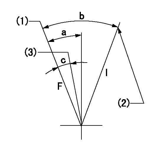
F:Full speed
I:Idle
(1)Set the pump speed at aa. ( At delivery )
(2)Stopper bolt setting
(3)Set the pump speed at bb.
----------
aa=905r/min bb=750r/min
----------
a=11deg+-5deg b=41deg+-5deg c=9deg+-5deg
----------
aa=905r/min bb=750r/min
----------
a=11deg+-5deg b=41deg+-5deg c=9deg+-5deg
Stop lever angle

N:Pump normal
S:Stop the pump.
(1)Normal
----------
----------
a=26.5deg+-5deg b=53deg+-5deg
----------
----------
a=26.5deg+-5deg b=53deg+-5deg
0000001501 GOV FULL LOAD ADJUSTMENT
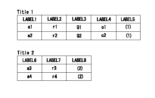
Title1:Full load stopper adjustment
Title2:Governor set speed
LABEL1:Distinguishing
LABEL2:Pump speed (r/min)
LABEL3:Ave. injection quantity (mm3/st)
LABEL4:Max. var. bet. cyl.
LABEL5:Remarks
LABEL6:Distinguishing
LABEL7:Governor set speed (r/min)
LABEL8:Remarks
(1)Adjustment conditions are the same as those for measuring injection quantity.
(2)-
----------
----------
a1=A a2=C r1=750r/min r2=750r/min Q1=96.5+-2mm3/st Q2=81.6+-2mm3/st c1=+-3% c2=+-3% a3=18 a4=15 r3=950r/min r4=750r/min
----------
----------
a1=A a2=C r1=750r/min r2=750r/min Q1=96.5+-2mm3/st Q2=81.6+-2mm3/st c1=+-3% c2=+-3% a3=18 a4=15 r3=950r/min r4=750r/min
Timing setting

(1)Pump vertical direction
(2)Position of coupling's threaded hole at No 1 cylinder's beginning of injection
(3)-
(4)-
----------
----------
a=(60deg)
----------
----------
a=(60deg)
Information:
Keypad
Keypad (6) is used to control the information that is shown on upper display (4) and lower display (5). The seven keys have two sets of functions, normal functions and service functions. For a description of the service functions of the keys; see the topic Service Mode. The normal functions of the keys are: Left Key- This key only functions when the GSC is in service mode. See the topic Service Mode. Phase Select Key- Selects which phase of the generator output is shown on the GSC. Pressing this key allows the operator to check the voltage, current, and frequency of each phase one at a time. Engine Meter Key- Stops the scrolling of engine conditions on lower display (5) and continuously shows the value for one particular engine condition. The pointer flashes to indicate scrolling is stopped. Pressing the key again, resumes the scrolling of engine conditions. Lamp Test Key- Performs a lamp test on the GSC and the optional alarm module. On the GSC the eight fault indicators are ON continuously, every segment of upper display (4) and lower display (5) are ON. On the optional alarm module all of the indicators are ON and the horn sounds. Alarm Codes Key- If the fault alarm indicator (3) is FLASHING, pressing this key causes the upper display (4) to show the corresponding alarm fault code. Pressing this key again, resumes the showing of generator output information on the upper display (4). If the fault alarm indicator (3) is OFF, this key has no function. For more information on alarm fault codes, see the topic Fault Description. Exit Key- This key only functions when the GSC is in service mode. See the topic Service Mode. Service Mode Key- Pressing this key causes the GSC to enter service mode. See the topic Service Mode.Engine Protection Controls
Engine and generator operating conditions and parameters are monitored and displayed on the Generator Set Control (GSC) Panel. The GSC detects faults that are alarm and shutdown conditions.The engine will continue to run when an alarm condition fault is displayed. The engine will automatically shut down if one of the following faults is detected and displayed.* Low oil pressure,* High coolant temperature,* Engine overspeed,* Low coolant level (if provided),* Engine overcrank.The activation of the Emergency Stop Push Button (ESPB) is also provided on the control panel.Fault Indicators
The eight fault indicators, located on the front of the GSC, are used to show and describe a fault that is present. * The yellow fault alarm indicator flashes when the GSC detects a fault that is an alarm condition. The engine continues to run and start. The fault alarm indicator is accompanied by an alarm fault code that is shown on the upper display when the Alarm Codes Key is pressed. Refer to Service Manual SENR5827 for fault code descriptions. * A red fault shutdown indicator flashes when the GSC detects a fault that is a shutdown condition. The engine is shutdown if it is running
Have questions with 101692-9310?
Group cross 101692-9310 ZEXEL
Nissan-Diesel
101692-9310
9 400 616 064
16712Z5509
INJECTION-PUMP ASSEMBLY
FE6T05
FE6T05