Information injection-pump assembly
ZEXEL
101692-3970
1016923970
KOMATSU
6207711371
6207711371
Rating:
Cross reference number
ZEXEL
101692-3970
1016923970
KOMATSU
6207711371
6207711371
Zexel num
Bosch num
Firm num
Name
101692-3970
6207711371 KOMATSU
INJECTION-PUMP ASSEMBLY
S6D95L * K
S6D95L * K
Calibration Data:
Adjustment conditions
Test oil
1404 Test oil ISO4113 or {SAEJ967d}
1404 Test oil ISO4113 or {SAEJ967d}
Test oil temperature
degC
40
40
45
Nozzle and nozzle holder
105780-8140
Bosch type code
EF8511/9A
Nozzle
105780-0000
Bosch type code
DN12SD12T
Nozzle holder
105780-2080
Bosch type code
EF8511/9
Opening pressure
MPa
17.2
Opening pressure
kgf/cm2
175
Injection pipe
Outer diameter - inner diameter - length (mm) mm 6-2-600
Outer diameter - inner diameter - length (mm) mm 6-2-600
Tester oil delivery pressure
kPa
157
157
157
Tester oil delivery pressure
kgf/cm2
1.6
1.6
1.6
Direction of rotation (viewed from drive side)
Right R
Right R
Injection timing adjustment
Direction of rotation (viewed from drive side)
Right R
Right R
Injection order
1-5-3-6-
2-4
Pre-stroke
mm
3.6
3.55
3.65
Beginning of injection position
Drive side NO.1
Drive side NO.1
Difference between angles 1
Cal 1-5 deg. 60 59.5 60.5
Cal 1-5 deg. 60 59.5 60.5
Difference between angles 2
Cal 1-3 deg. 120 119.5 120.5
Cal 1-3 deg. 120 119.5 120.5
Difference between angles 3
Cal 1-6 deg. 180 179.5 180.5
Cal 1-6 deg. 180 179.5 180.5
Difference between angles 4
Cyl.1-2 deg. 240 239.5 240.5
Cyl.1-2 deg. 240 239.5 240.5
Difference between angles 5
Cal 1-4 deg. 300 299.5 300.5
Cal 1-4 deg. 300 299.5 300.5
Injection quantity adjustment
Adjusting point
A
Rack position
10.8
Pump speed
r/min
1100
1100
1100
Average injection quantity
mm3/st.
42.5
41.5
43.5
Max. variation between cylinders
%
0
-2.5
2.5
Basic
*
Fixing the lever
*
Injection quantity adjustment_02
Adjusting point
-
Rack position
10.4+-0.
5
Pump speed
r/min
425
425
425
Average injection quantity
mm3/st.
12.5
11.5
13.5
Max. variation between cylinders
%
0
-15
15
Fixing the rack
*
Remarks
Adjust only variation between cylinders; adjust governor according to governor specifications.
Adjust only variation between cylinders; adjust governor according to governor specifications.
Test data Ex:
Governor adjustment
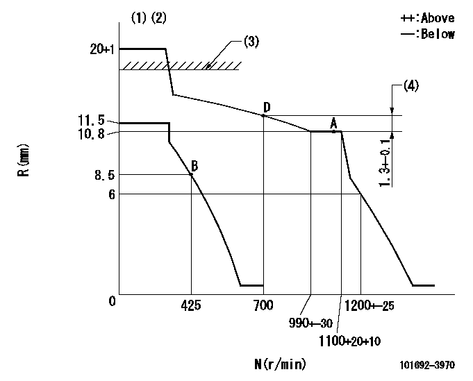
N:Pump speed
R:Rack position (mm)
(1)Target notch: K
(2)The torque control spring must does not have a set force.
(3)RACK LIMIT: RAL
(4)Rack difference between N = N1 and N = N2
----------
K=4 RAL=15+0.2mm N1=1100r/min N2=700r/min
----------
----------
K=4 RAL=15+0.2mm N1=1100r/min N2=700r/min
----------
Speed control lever angle

F:Full speed
I:Idle
S:Stop
----------
----------
a=9deg+-5deg b=32deg+-3deg c=35deg+-5deg
----------
----------
a=9deg+-5deg b=32deg+-3deg c=35deg+-5deg
Stop lever angle

N:Pump normal
S:Stop the pump.
----------
----------
a=28deg+-5deg b=53deg+-5deg
----------
----------
a=28deg+-5deg b=53deg+-5deg
Timing setting

(1)Pump vertical direction
(2)Position of key groove at No 1 cylinder's beginning of injection
(3)Stamp aligning marks on the pump housing flange.
(4)-
(5)-
----------
----------
a=59deg36min+-3deg b=0deg24min+-30min
----------
----------
a=59deg36min+-3deg b=0deg24min+-30min
Information:
Cleaning Air Filter Elements
The primary element (Caterpillar air filters) can be cleaned several times before replacement. The element, when cleaned, should be thoroughly checked for rips or tears in the filter material.Replace the primary element at least every year regardless of the number of operating hours the element has accumulated.
Do not clean filter elements by bumping or tapping.Do not use filter elements with damaged pleats, gaskets or seals. Engine damage could result.
Filter elements can be cleaned with air pressure, 205 kPa (30 psi) maximum, or water pressure, 280 kPa (40 psi) maximum, or detergent washing. Have spare elements on hand to use while cleaning used elements.* Direct air or water along the length of the pleats inside and outside of filter element. The element can be washed in warm water and nonsudsing household detergent, such as automatic dishwasher detergent. Rinse inside and outside the pleats. The filter should then be thoroughly air dried and inspected. * Inspect the filter elements after cleaning for any rips, tears or damage. Insert a light inside of the clean, dry element. Do not use a filter element with damaged pleats, gaskets or seals. Discard the element if damaged. * Wrap and store the clean filter elements in a clean, dry place.For more information on air cleaner element cleaning, refer to SEBF8062, Guideline for Reusable Parts-Cleaning and Inspection of Air Filters.Belts
Check/Adjust
Inspect the condition and adjustment of alternator and accessory drive belts. Examine all drive belts for wear and replace if they show any signs of wear. Loose or worn pulley grooves cause belt slippage and low accessory drive speed. If belts are too loose, they vibrate enough to cause unnecessary wear on the belts and pulleys and possibly slip enough to cause overheating.If belts are too tight, unnecessary stresses are placed upon the pulley bearings and belts which might shorten the life of both.If one belt in a set requires replacement, always install a new matched set of belts. Never replace just the worn belt. If only the worn belt is replaced, the new belt will carry all the load, as it will not be stretched as much as the older belts. All the belts will fail in rapid succession.Remove the belt guard. Inspect the condition and adjustment of alternator belts and accessory drive belts (if equipped).To check the belt tension, apply 110 Newton (25 lb) force, perpendicular to the belt, midway between the driving and driven pulley. Measure the belt deflection. Correctly adjusted belts will deflect 15 to 20 mm (9/16 to 7/8 inch).If the belt does not require replacement or adjustment, install the belt guard. If the belt requires adjustment or replacement, perform the following procedure to adjust the belt tension.
Typical belt assembly mounting bolt (1) and adjusting nuts (2).1. Loosen the mounting bolt (1) and the locknut on the adjusting bolt.2. Turn the adjusting nuts (2) to increase or decrease the belt tension.3. Tighten the adjusting bolt locknut. Tighten the mounting bolts. Refer to the Torque Specifications in
Have questions with 101692-3970?
Group cross 101692-3970 ZEXEL
Komatsu
Komatsu
101692-3970
6207711371
INJECTION-PUMP ASSEMBLY
S6D95L
S6D95L