Information injection-pump assembly
BOSCH
F 019 Z10 512
f019z10512
ZEXEL
101692-3960
1016923960
KOMATSU
6207711321
6207711321
Rating:
Service parts 101692-3960 INJECTION-PUMP ASSEMBLY:
1.
_
5.
AUTOM. ADVANCE MECHANIS
6.
COUPLING PLATE
7.
COUPLING PLATE
8.
_
9.
_
11.
Nozzle and Holder
12.
Open Pre:MPa(Kqf/cm2)
19.6(200)
15.
NOZZLE SET
Cross reference number
BOSCH
F 019 Z10 512
f019z10512
ZEXEL
101692-3960
1016923960
KOMATSU
6207711321
6207711321
Zexel num
Bosch num
Firm num
Name
101692-3960
F 019 Z10 512
6207711321 KOMATSU
INJECTION-PUMP ASSEMBLY
S6D95L * K
S6D95L * K
Calibration Data:
Adjustment conditions
Test oil
1404 Test oil ISO4113 or {SAEJ967d}
1404 Test oil ISO4113 or {SAEJ967d}
Test oil temperature
degC
40
40
45
Nozzle and nozzle holder
105780-8140
Bosch type code
EF8511/9A
Nozzle
105780-0000
Bosch type code
DN12SD12T
Nozzle holder
105780-2080
Bosch type code
EF8511/9
Opening pressure
MPa
17.2
Opening pressure
kgf/cm2
175
Injection pipe
Outer diameter - inner diameter - length (mm) mm 6-2-600
Outer diameter - inner diameter - length (mm) mm 6-2-600
Tester oil delivery pressure
kPa
157
157
157
Tester oil delivery pressure
kgf/cm2
1.6
1.6
1.6
Direction of rotation (viewed from drive side)
Right R
Right R
Injection timing adjustment
Direction of rotation (viewed from drive side)
Right R
Right R
Injection order
1-5-3-6-
2-4
Pre-stroke
mm
3.6
3.55
3.65
Beginning of injection position
Drive side NO.1
Drive side NO.1
Difference between angles 1
Cal 1-5 deg. 60 59.5 60.5
Cal 1-5 deg. 60 59.5 60.5
Difference between angles 2
Cal 1-3 deg. 120 119.5 120.5
Cal 1-3 deg. 120 119.5 120.5
Difference between angles 3
Cal 1-6 deg. 180 179.5 180.5
Cal 1-6 deg. 180 179.5 180.5
Difference between angles 4
Cyl.1-2 deg. 240 239.5 240.5
Cyl.1-2 deg. 240 239.5 240.5
Difference between angles 5
Cal 1-4 deg. 300 299.5 300.5
Cal 1-4 deg. 300 299.5 300.5
Injection quantity adjustment
Adjusting point
A
Rack position
10.8
Pump speed
r/min
1100
1100
1100
Average injection quantity
mm3/st.
42.5
41.5
43.5
Max. variation between cylinders
%
0
-2.5
2.5
Basic
*
Fixing the lever
*
Injection quantity adjustment_02
Adjusting point
-
Rack position
10.4+-0.
5
Pump speed
r/min
425
425
425
Average injection quantity
mm3/st.
12.5
11.5
13.5
Max. variation between cylinders
%
0
-15
15
Fixing the rack
*
Remarks
Adjust only variation between cylinders; adjust governor according to governor specifications.
Adjust only variation between cylinders; adjust governor according to governor specifications.
Test data Ex:
Governor adjustment
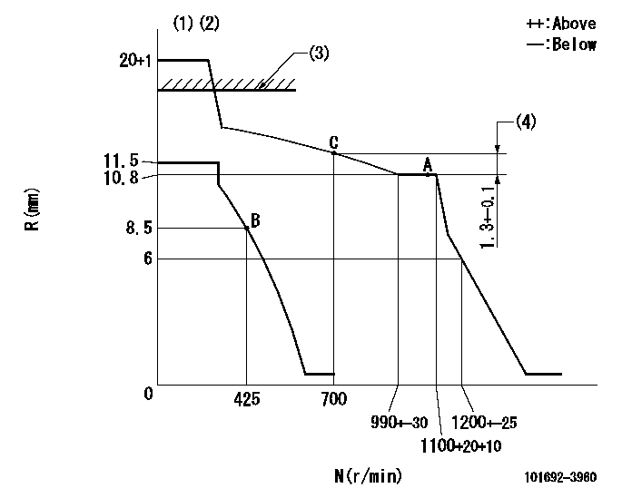
N:Pump speed
R:Rack position (mm)
(1)Target notch: K
(2)The torque control spring must does not have a set force.
(3)RACK LIMIT: RAL
(4)Rack difference between N = N1 and N = N2
----------
K=4 RAL=15+0.2mm N1=1100r/min N2=700r/min
----------
----------
K=4 RAL=15+0.2mm N1=1100r/min N2=700r/min
----------
Speed control lever angle
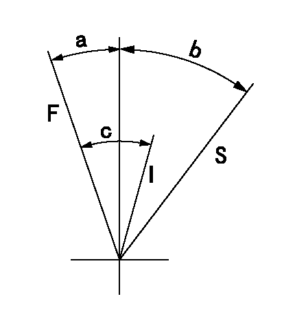
F:Full speed
I:Idle
S:Stop
----------
----------
a=9deg+-5deg b=32deg+-3deg c=35deg+-5deg
----------
----------
a=9deg+-5deg b=32deg+-3deg c=35deg+-5deg
Timing setting
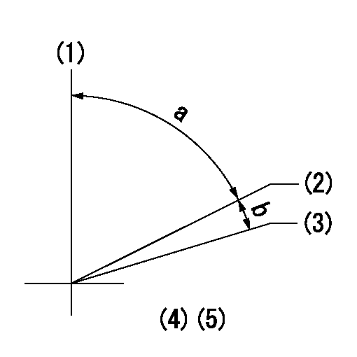
(1)Pump vertical direction
(2)Position of key groove at No 1 cylinder's beginning of injection
(3)Stamp aligning marks on the pump housing flange.
(4)-
(5)-
----------
----------
a=59deg36min+-3deg b=0deg24min+-30min
----------
----------
a=59deg36min+-3deg b=0deg24min+-30min
Information:
Priming the Fuel System
Fuel leaked or spilled on to hot surfaces or electrical components can cause a fire. Clean up fuel spills immediately.
Prime the fuel system to fill dry fuel filters and purge trapped air. The fuel system requires priming after:* being run dry* storage* fuel filter cleaning/replacement If the engine does not have a fuel priming pump, go to step 4.1. Unlock and operate the priming pump until a resistance is felt. A considerable number of pump strokes may be required.2. Push in and hand-tighten the plunger.3. Crank the engine. If the engine starts, but runs rough, continue running the engine at low idle until the engine runs smoothly.
Do not crank the engine for more than 30 seconds. If the engine does not start, allow the starter motor to cool for two minutes before cranking again.
If the engine will not start, or once started, continues to misfire or smoke, further priming is necessary. Repeat steps 1 through 3. If operating problems persist after repeating steps 1 through 3, further priming is necessary.4. Open the vent valve (if equipped) on the fuel injection pump housing.
DO NOT remove the plug in the fuel filter base (for the fuel pressure sending unit [if equipped]) to purge air from the fuel system. Periodic removal of the plug will result in increased wear of the threads in the fuel filter base and lead to fuel leakage.
5. Operate the priming pump until the flow of fuel from the vent valve is continuous and free of air bubbles. If the engine does not have a fuel priming pump, crank the engine until the fuel flows free of air bubbles. Do not crank the engine for more than 30 seconds. Allow the starter to cool for two minutes before cranking again.6. Close the vent valve. Push in and hand-tighten the plunger.7. Crank the engine. If the engine starts, but runs rough, continue running the engine at low idle until the engine runs smoothly. If the engine will not start, or once started, continues to misfire or smoke, further priming is necessary.8. Loosen the fuel line nuts, one at a time, at the valve cover base.
A fuel injection nozzle will be damaged if the top of the nozzle turns in the body. The engine will be damaged if a defective fuel injection nozzle is used because the fuel spray pattern that comes out of the nozzle will be incorrect. Fuel injection nozzles can be permanently damaged by twisting if only one wrench is used to loosen or tighten the fuel line nuts. Do NOT let the tops of the fuel nozzles turn when the fuel lines are loosened. Use one wrench to hold the nozzle and another to loosen the fuel line nut.
Operate the priming pump plunger until the flow of fuel from the fuel line is continuous and free of air bubbles. Push the plunger in and tighten by hand. If the engine does not have a fuel priming pump, crank the engine.Tighten each fuel
Have questions with 101692-3960?
Group cross 101692-3960 ZEXEL
Komatsu
Komatsu
101692-3960
F 019 Z10 512
6207711321
INJECTION-PUMP ASSEMBLY
S6D95L
S6D95L
