Information injection-pump assembly
BOSCH
9 400 610 312
9400610312
ZEXEL
101692-3934
1016923934
KOMATSU
6206711480
6206711480
Rating:
Service parts 101692-3934 INJECTION-PUMP ASSEMBLY:
1.
_
5.
AUTOM. ADVANCE MECHANIS
6.
COUPLING PLATE
7.
COUPLING PLATE
8.
_
9.
_
11.
Nozzle and Holder
6206-11-3100
12.
Open Pre:MPa(Kqf/cm2)
19.6{200}
15.
NOZZLE SET
Cross reference number
BOSCH
9 400 610 312
9400610312
ZEXEL
101692-3934
1016923934
KOMATSU
6206711480
6206711480
Zexel num
Bosch num
Firm num
Name
101692-3934
9 400 610 312
6206711480 KOMATSU
INJECTION-PUMP ASSEMBLY
6D95L K 14BE INJECTION PUMP ASSY PE6A PE
6D95L K 14BE INJECTION PUMP ASSY PE6A PE
Calibration Data:
Adjustment conditions
Test oil
1404 Test oil ISO4113 or {SAEJ967d}
1404 Test oil ISO4113 or {SAEJ967d}
Test oil temperature
degC
40
40
45
Nozzle and nozzle holder
105780-8140
Bosch type code
EF8511/9A
Nozzle
105780-0000
Bosch type code
DN12SD12T
Nozzle holder
105780-2080
Bosch type code
EF8511/9
Opening pressure
MPa
17.2
Opening pressure
kgf/cm2
175
Injection pipe
Outer diameter - inner diameter - length (mm) mm 6-2-600
Outer diameter - inner diameter - length (mm) mm 6-2-600
Tester oil delivery pressure
kPa
157
157
157
Tester oil delivery pressure
kgf/cm2
1.6
1.6
1.6
Direction of rotation (viewed from drive side)
Right R
Right R
Injection timing adjustment
Direction of rotation (viewed from drive side)
Right R
Right R
Injection order
1-5-3-6-
2-4
Pre-stroke
mm
3.6
3.55
3.65
Beginning of injection position
Drive side NO.1
Drive side NO.1
Difference between angles 1
Cal 1-5 deg. 60 59.5 60.5
Cal 1-5 deg. 60 59.5 60.5
Difference between angles 2
Cal 1-3 deg. 120 119.5 120.5
Cal 1-3 deg. 120 119.5 120.5
Difference between angles 3
Cal 1-6 deg. 180 179.5 180.5
Cal 1-6 deg. 180 179.5 180.5
Difference between angles 4
Cyl.1-2 deg. 240 239.5 240.5
Cyl.1-2 deg. 240 239.5 240.5
Difference between angles 5
Cal 1-4 deg. 300 299.5 300.5
Cal 1-4 deg. 300 299.5 300.5
Injection quantity adjustment
Adjusting point
A
Rack position
9.3
Pump speed
r/min
1250
1250
1250
Average injection quantity
mm3/st.
31.8
30.8
32.8
Max. variation between cylinders
%
0
-2.5
2.5
Basic
*
Fixing the lever
*
Injection quantity adjustment_02
Adjusting point
D
Rack position
8.5+-0.5
Pump speed
r/min
500
500
500
Average injection quantity
mm3/st.
8
7
9
Max. variation between cylinders
%
0
-15
15
Fixing the rack
*
Remarks
Adjust only variation between cylinders; adjust governor according to governor specifications.
Adjust only variation between cylinders; adjust governor according to governor specifications.
Test data Ex:
Governor adjustment
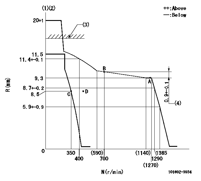
N:Pump speed
R:Rack position (mm)
(1)Target notch: K
(2)Tolerance for racks not indicated: +-0.05mm.
(3)RACK CAP: R1
(4)Rack difference between N = N1 and N = N2
----------
K=17 R1=(17.5)mm N1=1250r/min N2=700r/min
----------
----------
K=17 R1=(17.5)mm N1=1250r/min N2=700r/min
----------
Speed control lever angle
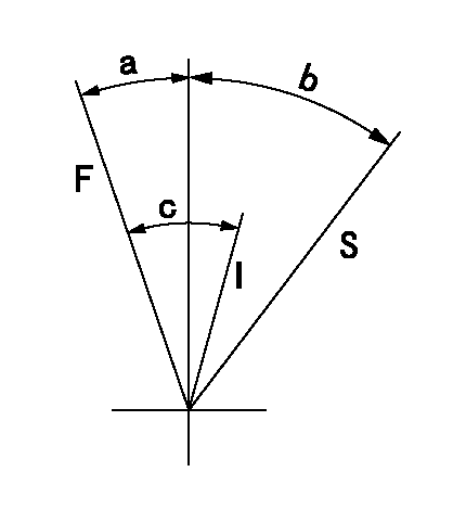
F:Full speed
I:Idle
S:Stop
----------
----------
a=23deg+-5deg b=32deg+-3deg c=29deg+-5deg
----------
----------
a=23deg+-5deg b=32deg+-3deg c=29deg+-5deg
Timing setting
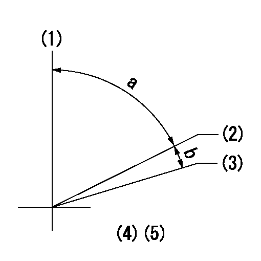
(1)Pump vertical direction
(2)Position of key groove at No 1 cylinder's beginning of injection
(3)Stamp aligning marks on the pump housing flange.
(4)-
(5)-
----------
----------
a=59deg36min+-3deg b=0deg24min+-30min
----------
----------
a=59deg36min+-3deg b=0deg24min+-30min
Information:
For all marine transmission lubrication and maintenance activities, refer to your marine transmission or vessel OEM literature.Use fuel consumption, service hours, or calendar time, whichever occurs first, to determine maintenance intervals. Experience has shown that maintenance intervals are most accurately scheduled on the basis of fuel consumed rather than service hours.Daily
Walk-Around Inspection - Inspect engine for leaks and loose connections Engine Crankcase - Check oil level Cooling System - Check coolant level Air Cleaner - Check service indicator/Service air cleaner when needed Air Starter (If Equipped) - Check lubricator oil level Clutch (If Equipped) - Check/Adjust/Lubricate Marine Transmission - Check oil levelEvery 2550 L (675 gal) of Fuel or 50 Hours
Zinc Rods - Inspect/ReplaceFirst 12,750 L (3375 gal) of Fuel or 250 Hours
1 Valve Lash - Check/Adjust (at the first oil change interval)Every 12,750 L (3375 gal) of Fuel or 250 Hours or Yearly
1 Scheduled Oil Sampling (S O S) - Obtain Sample and analysis1 Engine Crankcase - Replace oil and filter(s)1 Crankcase Breathers - Clean Fuel System - Clean primary fuel filter (if equipped)/Replace final fuel filter Fuel Tank - Drain water and sediment Cooling System (Conventional HD Coolant Only) - Test for SCA concentration OR obtain Level I coolant analysis/Add SCA if necessary Air Cleaner - Clean/Replace air filter elements Belts - Check/Adjust/Replace Hoses and Clamps - Inspect/Replace Batteries - Clean/Check (if required)Every 51,000 L (13,500 gal) Of Fuel Or 1000 Hours
Engine Protection Devices - Inspect/Check Magnetic Pickup - Inspect/AdjustEvery 153,500 L (40,500 gal) Of Fuel Or 3000 Hours
Water Temperature Regulators (Thermostats) - Replace Cooling System (Extended Life Coolant Only) - Add Extender2 Cooling System (Conventional HD Coolant Only) - Drain/Clean/Replace coolant Engine Mounts - Inspect Crankshaft Vibration Damper - Inspect Valve Lash, Valve Rotators - Check/Adjust Fuel Ratio Control, Set Point, and Low Idle - Check/Adjust PAR Analysis - ObtainEvery 256,000 L (67,500 gal) Of Fuel Or 5000 Hours
Fuel Injection Nozzles - Test/Exchange Jacket Water Pump - Inspect/Rebuild or Exchange Raw/Sea Water Pump - Inspect/Rebuild or Exchange Alternator - Inspect/Rebuild or Exchange Starting Motor - Inspect/Rebuild or Exchange Air Compressor (If Equipped) - Inspect/Rebuild or Exchange Turbocharger - Clean/Inspect/CheckEvery 6000 Hours Or Four Years
Cooling System (Extended Life Coolant Only) - Drain/Flush/Replace CoolantOverhaul
Overhaul Considerations13408 Marine Engines that are equipped with the deep oil sump [87 L (92 qt)] may perform this maintenance after 25,500 L (6750 gal) of fuel or 500 Hours.2If a commercial HD coolant/antifreeze meeting ASTM D4985 specifications is used, or if a mixture of commercial SCA and water is used, this maintenance should be performed at a maximum of One Year.
Have questions with 101692-3934?
Group cross 101692-3934 ZEXEL
Komatsu
Komatsu
101692-3934
9 400 610 312
6206711480
INJECTION-PUMP ASSEMBLY
6D95L
6D95L
