Information injection-pump assembly
BOSCH
9 400 616 051
9400616051
ZEXEL
101692-3820
1016923820
KOMATSU
6207711230
6207711230
Rating:
Cross reference number
BOSCH
9 400 616 051
9400616051
ZEXEL
101692-3820
1016923820
KOMATSU
6207711230
6207711230
Zexel num
Bosch num
Firm num
Name
Calibration Data:
Adjustment conditions
Test oil
1404 Test oil ISO4113 or {SAEJ967d}
1404 Test oil ISO4113 or {SAEJ967d}
Test oil temperature
degC
40
40
45
Nozzle and nozzle holder
105780-8140
Bosch type code
EF8511/9A
Nozzle
105780-0000
Bosch type code
DN12SD12T
Nozzle holder
105780-2080
Bosch type code
EF8511/9
Opening pressure
MPa
17.2
Opening pressure
kgf/cm2
175
Injection pipe
Outer diameter - inner diameter - length (mm) mm 6-2-600
Outer diameter - inner diameter - length (mm) mm 6-2-600
Overflow valve
132424-0620
Overflow valve opening pressure
kPa
157
123
191
Overflow valve opening pressure
kgf/cm2
1.6
1.25
1.95
Tester oil delivery pressure
kPa
157
157
157
Tester oil delivery pressure
kgf/cm2
1.6
1.6
1.6
Direction of rotation (viewed from drive side)
Right R
Right R
Injection timing adjustment
Direction of rotation (viewed from drive side)
Right R
Right R
Injection order
1-5-3-6-
2-4
Pre-stroke
mm
3.2
3.15
3.25
Rack position
Point A R=A
Point A R=A
Beginning of injection position
Drive side NO.1
Drive side NO.1
Difference between angles 1
Cal 1-5 deg. 60 59.5 60.5
Cal 1-5 deg. 60 59.5 60.5
Difference between angles 2
Cal 1-3 deg. 120 119.5 120.5
Cal 1-3 deg. 120 119.5 120.5
Difference between angles 3
Cal 1-6 deg. 180 179.5 180.5
Cal 1-6 deg. 180 179.5 180.5
Difference between angles 4
Cyl.1-2 deg. 240 239.5 240.5
Cyl.1-2 deg. 240 239.5 240.5
Difference between angles 5
Cal 1-4 deg. 300 299.5 300.5
Cal 1-4 deg. 300 299.5 300.5
Injection quantity adjustment
Adjusting point
A
Rack position
10.5
Pump speed
r/min
1025
1025
1025
Average injection quantity
mm3/st.
74
73
75
Max. variation between cylinders
%
0
-2.5
2.5
Basic
*
Fixing the lever
*
Injection quantity adjustment_02
Adjusting point
-
Rack position
8.3+-0.5
Pump speed
r/min
450
450
450
Average injection quantity
mm3/st.
12.5
11.5
13.5
Max. variation between cylinders
%
0
-15
15
Fixing the rack
*
Remarks
Adjust only variation between cylinders; adjust governor according to governor specifications.
Adjust only variation between cylinders; adjust governor according to governor specifications.
Test data Ex:
Governor adjustment
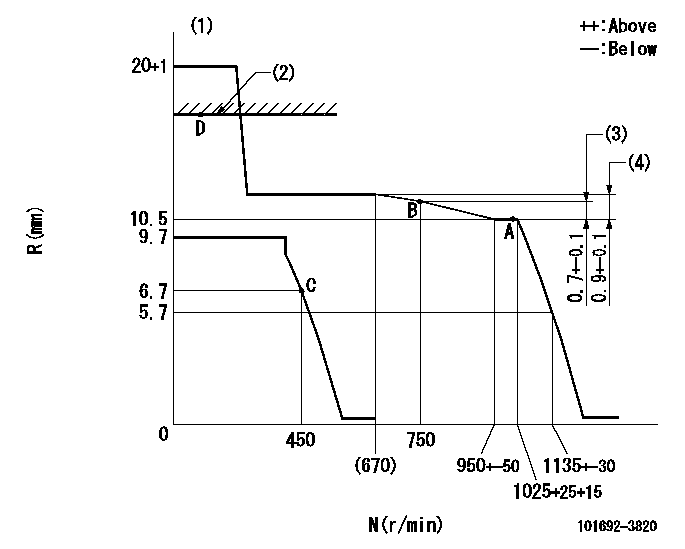
N:Pump speed
R:Rack position (mm)
(1)Target notch: K
(2)RACK LIMIT: RAL
(3)Rack difference from N = N1
(4)Rack difference between N = N2 and N = N3
----------
K=15 RAL=15+0.2mm N1=1025r/min N2=1025r/min N3=350r/min
----------
----------
K=15 RAL=15+0.2mm N1=1025r/min N2=1025r/min N3=350r/min
----------
Speed control lever angle
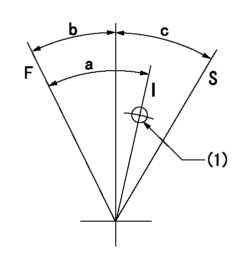
F:Full speed
I:Idle
S:Stop
(1)Use the hole at R = aa
----------
aa=80mm
----------
a=31deg+-5deg b=17deg+-3deg c=32deg+-3deg
----------
aa=80mm
----------
a=31deg+-5deg b=17deg+-3deg c=32deg+-3deg
Stop lever angle

N:Pump normal
S:Stop the pump.
----------
----------
a=1deg+-5deg b=53deg+-5deg
----------
----------
a=1deg+-5deg b=53deg+-5deg
Timing setting

(1)Pump vertical direction
(2)Position of key groove at No 1 cylinder's beginning of injection
(3)Stamp aligning marks on the pump housing flange.
(4)-
(5)-
----------
----------
a=58deg+-3deg b=2deg+-30min
----------
----------
a=58deg+-3deg b=2deg+-30min
Information:
Always determine the cause of the engine shutdown. Make necessary repairs before attempting restarting the engine.
Air Shutoff Solenoid (If Equipped)
This optional solenoid is located on top of the engine in the air inlet system. When the solenoid is activated, the solenoid mechanically shuts off inlet air to the engine. The solenoid can only be activated by the overspeed switch or the emergency stop switch. The air shutoff must be reset before the engine can be restarted.Fuel Shutoff Solenoid
This solenoid is located on the governor or on the fuel injection pump. When the solenoid is activated, the solenoid moves the fuel rack (either directly or through the governor) to the FUEL OFF position.Overspeed Shutoffs
Magnetic pickup, (1), mounted in the flywheel housing (2).A magnetic pickup mounted in the flywheel housing senses the passage of the flywheel ring gear teeth. Should the engine speed increase above the overspeed setting of the Electronic Overspeed Switch (118 percent of rated engine speed), the magnetic pickup will sense the overspeed and send a signal to the Electronic Overspeed Switch. The Electronic Overspeed Switch activates both the air (if equipped) and fuel shutoff solenoids.The shutoffs must be reset before the engine will restart. A reset button on the Electronic Overspeed Switch (in the junction box) must be pushed to open the overspeed switch. The air shutoff lever (at the top of the air inlet housing) must be manually reset.Oil Pressure Switches
Typical example of oil pressure switches, mounted in the rear of the junction box.An oil pressure switch has wires connected to the electrical system for alarm or shutoff functions. The oil pressure switch senses oil pressure at the bearing oil gallery. If sufficient oil pressure is not achieved after engine starting, or if the engine has been running normally and then loses oil pressure, the fuel shutoff solenoid is energized to shut the engine off. No resetting procedure is required.Engine Step Oil Pressure
This is an adjustable engine speed setting that protects the engine from a failure caused by too little oil pressure for a specified speed range. This option requires two different oil pressure switches. One switch has a high pressure rating- when the engine is running above the speed setting, the engine must maintain oil pressure higher than the switch rating. The other switch has a low pressure rating- an engine running below the speed setting must maintain oil pressure above the low switch rating.In an automatic start/stop system, an automatic reset switch is used.Water Temperature Contactor Switch
The water temperature contactor switch is located in the cylinder head. High water temperature closes the switch to activate an alarm or fuel shutoff. No resetting is required. The switch opens as the coolant cools.
The sensing element must be submerged in the coolant to operate. Be sure to have an adequate water supply in the jacket water system, or engine damage could result.
Water Level Switch
Typical water level switch, mounted on the side of an expansion tank.If the coolant water level drops below the minimum level, the switch