Information injection-pump assembly
ZEXEL
101692-3800
1016923800
Rating:
Cross reference number
ZEXEL
101692-3800
1016923800
Zexel num
Bosch num
Firm num
Name
101692-3800
KOMATSU
INJECTION-PUMP ASSEMBLY
6D95L *
6D95L *
Calibration Data:
Adjustment conditions
Test oil
1404 Test oil ISO4113 or {SAEJ967d}
1404 Test oil ISO4113 or {SAEJ967d}
Test oil temperature
degC
40
40
45
Nozzle and nozzle holder
105780-8140
Bosch type code
EF8511/9A
Nozzle
105780-0000
Bosch type code
DN12SD12T
Nozzle holder
105780-2080
Bosch type code
EF8511/9
Opening pressure
MPa
17.2
Opening pressure
kgf/cm2
175
Injection pipe
Outer diameter - inner diameter - length (mm) mm 6-2-600
Outer diameter - inner diameter - length (mm) mm 6-2-600
Tester oil delivery pressure
kPa
157
157
157
Tester oil delivery pressure
kgf/cm2
1.6
1.6
1.6
Direction of rotation (viewed from drive side)
Right R
Right R
Injection timing adjustment
Direction of rotation (viewed from drive side)
Right R
Right R
Injection order
1-5-3-6-
2-4
Pre-stroke
mm
3.6
3.55
3.65
Beginning of injection position
Drive side NO.1
Drive side NO.1
Difference between angles 1
Cal 1-5 deg. 60 59.5 60.5
Cal 1-5 deg. 60 59.5 60.5
Difference between angles 2
Cal 1-3 deg. 120 119.5 120.5
Cal 1-3 deg. 120 119.5 120.5
Difference between angles 3
Cal 1-6 deg. 180 179.5 180.5
Cal 1-6 deg. 180 179.5 180.5
Difference between angles 4
Cyl.1-2 deg. 240 239.5 240.5
Cyl.1-2 deg. 240 239.5 240.5
Difference between angles 5
Cal 1-4 deg. 300 299.5 300.5
Cal 1-4 deg. 300 299.5 300.5
Injection quantity adjustment
Adjusting point
A
Rack position
10.3
Pump speed
r/min
900
900
900
Average injection quantity
mm3/st.
52
51
53
Max. variation between cylinders
%
0
-2.5
2.5
Basic
*
Fixing the rack
*
Injection quantity adjustment_02
Adjusting point
-
Rack position
9.1+-0.5
Pump speed
r/min
400
400
400
Average injection quantity
mm3/st.
10.5
9.5
11.5
Max. variation between cylinders
%
0
-15
15
Fixing the rack
*
Remarks
Adjust only variation between cylinders; adjust governor according to governor specifications.
Adjust only variation between cylinders; adjust governor according to governor specifications.
Test data Ex:
Governor adjustment
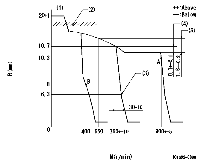
N:Pump speed
R:Rack position (mm)
(1)Target notch: K
(2)RACK CAP: R1
(3)Idle sub spring setting: L1.
(4)Rack difference between N = N1 and N = N2
(5)Rack difference to N = N3
----------
K=12 R1=(17.5)mm L1=6.3-0.5mm N1=800r/min N2=750r/min N3=800r/min
----------
----------
K=12 R1=(17.5)mm L1=6.3-0.5mm N1=800r/min N2=750r/min N3=800r/min
----------
Speed control lever angle
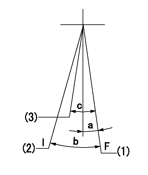
F:Full speed
I:Idle
(1)Pump speed = aa
(2)Stopper bolt setting
(3)Pump speed = bb
----------
aa=900r/min bb-750r/min
----------
a=2deg+-5deg b=22deg+-5deg c=6deg+-5deg
----------
aa=900r/min bb-750r/min
----------
a=2deg+-5deg b=22deg+-5deg c=6deg+-5deg
Stop lever angle
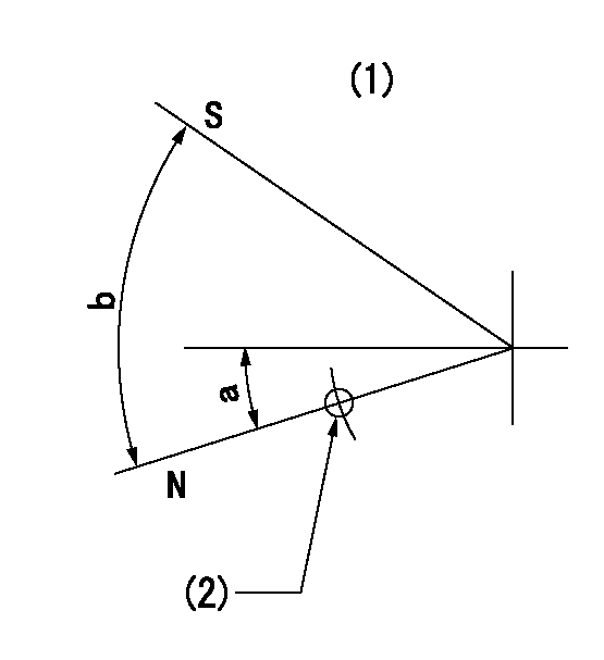
N:Pump normal
S:Stop the pump.
(1)No return spring
(2)Use hole at R = aa (left hand side)
----------
aa=27mm
----------
a=26.5deg+-5deg b=53deg+-5deg
----------
aa=27mm
----------
a=26.5deg+-5deg b=53deg+-5deg
Timing setting

(1)Pump vertical direction
(2)Position of key groove at No 1 cylinder's beginning of injection
(3)Stamp aligning marks on the pump housing flange.
(4)-
(5)-
----------
----------
a=59deg36min+-3deg b=0deg24min+-30min
----------
----------
a=59deg36min+-3deg b=0deg24min+-30min
Information:
Engine Lifting
When it is necessary to remove a component on an angle, remember that the capacity of an eyebolt is less as the angle between the supporting members and the object becomes less than 90 degrees. Eye Bolts and brackets should never be bent, and should only be loaded under tension.
Use a hoist to remove heavy components. Use an adjustable lifting beam to lift the engine. All supporting members (chains and cables) should be parallel to each other, and perpendicular as possible to the top of the object being lifted.Some removals require the use of lifting fixtures, to obtain proper balance and provide safe handling.To remove the engine ONLY, use the lifting eyes equipped with the engine.The lifting eyes are designed for the engine arrangement as sold. Modifying the lifting eyes and/or engine arrangement weight renders the lifting eyes and devices obsolete.If you modify the lifting eyes and/or engine arrangement weight, you are responsible for providing adequate lifting devices. Contact your Caterpillar dealer for information regarding fixtures for proper engine package lifting.Engine Storage
The following Engine Storage procedures and recommendations minimize the possibility of damage to engines stored for one year or less.When an engine is not started for several weeks, the lubricating oil drains from the cylinder walls and piston rings. Rust can then form on the cylinder liner surface, increasing engine wear and decreasing engine life.Special precautions should be used with engines remaining out of service for extended periods.After one year, a complete protection procedure must be followed if the engine is kept in storage longer. To prevent excessive engine wear:* Be sure all lubrication recommendations mentioned in the Maintenance Schedule intervals chart are completed.* If freezing temperatures are expected, check the cooling system for adequate protection against freezing. A 50/50 solution of Caterpillar (permanent-type) Antifreeze and approved water will give protection to -29°C (-20°F).If it will be impossible to start the engine periodically, consult your Caterpillar dealer for instructions to prepare your engine for longer storage periods.Refer to Storage Procedures For Caterpillar Products, SEHS9031, for more detailed information on engine storage.Engine and Marine Transmission Lifting
To remove the engine only, or the engine and marine gear together, use the lifting eyes on the engine.Marine Transmission Lifting
To remove the marine transmission only, use the eye bolts in the marine transmission housing.If a component resists removal, check to be certain all nuts and bolts have been removed and that an adjacent part is not interfering.Marine Transmission Storage
Transmission Storage Procedure
1. First, thoroughly clean the transmission and put on good quality paint.2. If the marine transmission is to be in storage for more than six months, add VCI oil at a rate of two percent of lube oil capacity. This will give additional protection from moisture.3. Operate the marine transmission for a short period to circulate oil.4. Cover and/or put tape over all openings.5. Put a heavy amount of multipurpose grease on all outside parts that move: linkage, etc.6. Put a waterproof or plastic cover over the unit.Transmission Procedure After Storage
1.
Have questions with 101692-3800?
Group cross 101692-3800 ZEXEL
Komatsu
101692-3800
INJECTION-PUMP ASSEMBLY
6D95L
6D95L