Information injection-pump assembly
ZEXEL
101692-3700
1016923700
KOMATSU
6206731110
6206731110
Rating:
Cross reference number
ZEXEL
101692-3700
1016923700
KOMATSU
6206731110
6206731110
Zexel num
Bosch num
Firm num
Name
Calibration Data:
Adjustment conditions
Test oil
1404 Test oil ISO4113 or {SAEJ967d}
1404 Test oil ISO4113 or {SAEJ967d}
Test oil temperature
degC
40
40
45
Nozzle and nozzle holder
105780-8140
Bosch type code
EF8511/9A
Nozzle
105780-0000
Bosch type code
DN12SD12T
Nozzle holder
105780-2080
Bosch type code
EF8511/9
Opening pressure
MPa
17.2
Opening pressure
kgf/cm2
175
Injection pipe
Outer diameter - inner diameter - length (mm) mm 6-2-600
Outer diameter - inner diameter - length (mm) mm 6-2-600
Tester oil delivery pressure
kPa
157
157
157
Tester oil delivery pressure
kgf/cm2
1.6
1.6
1.6
Direction of rotation (viewed from drive side)
Right R
Right R
Injection timing adjustment
Direction of rotation (viewed from drive side)
Right R
Right R
Injection order
1-5-3-6-
2-4
Pre-stroke
mm
3.6
3.55
3.65
Rack position
Point A R=A
Point A R=A
Beginning of injection position
Drive side NO.1
Drive side NO.1
Difference between angles 1
Cal 1-5 deg. 60 59.5 60.5
Cal 1-5 deg. 60 59.5 60.5
Difference between angles 2
Cal 1-3 deg. 120 119.5 120.5
Cal 1-3 deg. 120 119.5 120.5
Difference between angles 3
Cal 1-6 deg. 180 179.5 180.5
Cal 1-6 deg. 180 179.5 180.5
Difference between angles 4
Cyl.1-2 deg. 240 239.5 240.5
Cyl.1-2 deg. 240 239.5 240.5
Difference between angles 5
Cal 1-4 deg. 300 299.5 300.5
Cal 1-4 deg. 300 299.5 300.5
Injection quantity adjustment
Adjusting point
A
Rack position
10.5
Pump speed
r/min
1175
1175
1175
Average injection quantity
mm3/st.
36.8
35.8
37.8
Max. variation between cylinders
%
0
-2.5
2.5
Basic
*
Fixing the lever
*
Injection quantity adjustment_02
Adjusting point
-
Rack position
9.7+-0.5
Pump speed
r/min
350
350
350
Average injection quantity
mm3/st.
8
7
9
Max. variation between cylinders
%
0
-15
15
Fixing the rack
*
Remarks
Adjust only variation between cylinders; adjust governor according to governor specifications.
Adjust only variation between cylinders; adjust governor according to governor specifications.
Test data Ex:
Governor adjustment
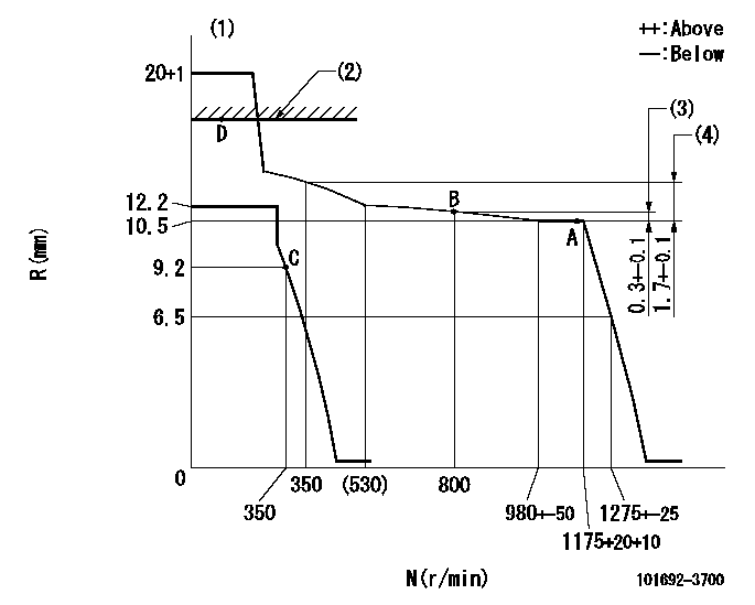
N:Pump speed
R:Rack position (mm)
(1)Target notch: K
(2)RACK CAP: R1
(3)Rack difference between N = N1 and N = N2
(4)Rack difference between N = N3 and N = N4
----------
K=7 R1=(17.5)mm N1=1175r/min N2=800r/min N3=1175r/min N4=350r/min
----------
----------
K=7 R1=(17.5)mm N1=1175r/min N2=800r/min N3=1175r/min N4=350r/min
----------
Speed control lever angle

F:Full speed
I:Idle
S:Stop
----------
----------
a=9deg+-5deg b=32deg+-3deg c=26deg+-5deg
----------
----------
a=9deg+-5deg b=32deg+-3deg c=26deg+-5deg
Timing setting

(1)Pump vertical direction
(2)Position of key groove at No 1 cylinder's beginning of injection
(3)Stamp aligning marks on the pump housing flange.
(4)-
(5)-
----------
----------
a=59deg36min+-3deg b=0deg24min+-30min
----------
----------
a=59deg36min+-3deg b=0deg24min+-30min
Information:
You must read and understand the warnings and instructions contained in the Safety section of this manual before performing any operation or maintenance procedures.Engine Compartment
Walk-Around Inspection
Inspect Engine for Leaks and Loose Connections
For maximum service life of your truck engine, make a thorough under the hood inspection before starting the engine. Look for such items as oil or coolant leaks, loose bolts, worn fan and accessory drive belts, loose connections and trash build-up. Remove trash build-up and have repairs made as needed. Check the fluid levels more frequently than the recommended maintenance intervals and continue to monitor fluid levels until any leak is found and fixed.* Wipe all fittings, caps and plugs before performing maintenance to reduce the chance of system contamination.* Inspect all lines, tubes and hoses carefully. Do not use your bare hands to check for leaks. Tighten all connections to the recommended torque.Inspect:* Radiator and ATAAC core for leaks and trash build-up.* Radiator and ATAAC air intake system hoses and elbows for cracks and loose clamps (especially in arctic conditions).* Fan and accessory drive belts for cracks, breaks or other damage (especially in arctic conditions). Inspect:* Water pump for coolant leaks. The water pump seal is lubricated by coolant and it is normal for a small amount of leakage to occur as the engine cools down and parts contract. If leaks are found, check the coolant level frequently and continue to monitor the level until the water pump is repaired. Excessive coolant leakage may indicate the need to replace the water pump seal. For removal and installation of water pumps and/or seals, see the Service Manual for this engine or consult Caterpillar.Inspect:* Lube system for leaks, such as front and rear crankshaft seals, oil pan, oil filters and valve covers.* Fuel system for leaks, loose fuel line fittings and loose or worn hoses.* Engine wiring and harnesses for loose connections and worn or frayed wires (especially in arctic conditions).* Engine electrical grounding system for good connections and condition. Some vehicles will use a starter to battery ground strap. If a starting motor change is made, consult Caterpillar to make sure that the proper grounding procedures are followed for that model starting motor.* All guards must be in place. Repair or replace missing or damaged guards.Engine Crankcase
Make sure you read and understand the information in the Safety and Lubricant Specifications sections of this Manual before you proceed with maintenance of the crankcase lube oil system.
Check Oil Level
The vehicle must be parked on a level surface to perform this maintenance procedure.
1. Check the oil level with the engine stopped. DO NOT check the oil level with the engine running. Refer to the Refill Capacities chart for the proper amount of oil at oil change time to determine the correct position on the dipstick for your application. If more oil than the specified Refill Capacity is required to reach the OPERATING RANGE (FULL) mark, consult Caterpillar. DO NOT OVERFILL above the OPERATING RANGE (FULL) mark on