Information injection-pump assembly
BOSCH
9 400 616 043
9400616043
ZEXEL
101692-3670
1016923670
KOMATSU
6206711550
6206711550
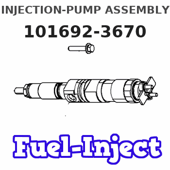
Rating:
Service parts 101692-3670 INJECTION-PUMP ASSEMBLY:
1.
_
5.
AUTOM. ADVANCE MECHANIS
6.
COUPLING PLATE
7.
COUPLING PLATE
8.
_
9.
_
11.
Nozzle and Holder
12.
Open Pre:MPa(Kqf/cm2)
19.6(200)
15.
NOZZLE SET
Cross reference number
BOSCH
9 400 616 043
9400616043
ZEXEL
101692-3670
1016923670
KOMATSU
6206711550
6206711550
Zexel num
Bosch num
Firm num
Name
Calibration Data:
Adjustment conditions
Test oil
1404 Test oil ISO4113 or {SAEJ967d}
1404 Test oil ISO4113 or {SAEJ967d}
Test oil temperature
degC
40
40
45
Nozzle and nozzle holder
105780-8140
Bosch type code
EF8511/9A
Nozzle
105780-0000
Bosch type code
DN12SD12T
Nozzle holder
105780-2080
Bosch type code
EF8511/9
Opening pressure
MPa
17.2
Opening pressure
kgf/cm2
175
Injection pipe
Outer diameter - inner diameter - length (mm) mm 6-2-600
Outer diameter - inner diameter - length (mm) mm 6-2-600
Overflow valve opening pressure
kPa
157
123
191
Overflow valve opening pressure
kgf/cm2
1.6
1.25
1.95
Tester oil delivery pressure
kPa
157
157
157
Tester oil delivery pressure
kgf/cm2
1.6
1.6
1.6
Direction of rotation (viewed from drive side)
Right R
Right R
Injection timing adjustment
Direction of rotation (viewed from drive side)
Right R
Right R
Injection order
1-5-3-6-
2-4
Pre-stroke
mm
3.6
3.55
3.65
Rack position
Point A R=A
Point A R=A
Beginning of injection position
Drive side NO.1
Drive side NO.1
Difference between angles 1
Cal 1-5 deg. 60 59.5 60.5
Cal 1-5 deg. 60 59.5 60.5
Difference between angles 2
Cal 1-3 deg. 120 119.5 120.5
Cal 1-3 deg. 120 119.5 120.5
Difference between angles 3
Cal 1-6 deg. 180 179.5 180.5
Cal 1-6 deg. 180 179.5 180.5
Difference between angles 4
Cyl.1-2 deg. 240 239.5 240.5
Cyl.1-2 deg. 240 239.5 240.5
Difference between angles 5
Cal 1-4 deg. 300 299.5 300.5
Cal 1-4 deg. 300 299.5 300.5
Injection quantity adjustment
Adjusting point
A
Rack position
9.7
Pump speed
r/min
1175
1175
1175
Average injection quantity
mm3/st.
34.1
33.1
35.1
Max. variation between cylinders
%
0
-2.5
2.5
Basic
*
Fixing the lever
*
Injection quantity adjustment_02
Adjusting point
-
Rack position
10.3+-0.
5
Pump speed
r/min
350
350
350
Average injection quantity
mm3/st.
10.5
9.5
11.5
Max. variation between cylinders
%
0
-15
15
Fixing the rack
*
Remarks
Adjust only variation between cylinders; adjust governor according to governor specifications.
Adjust only variation between cylinders; adjust governor according to governor specifications.
Test data Ex:
Governor adjustment
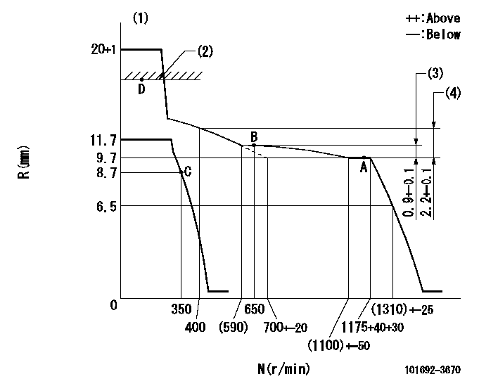
N:Pump speed
R:Rack position (mm)
(1)Notch fixed: K
(2)RACK CAP: R1
(3)Rack difference from N = N1
(4)Rack difference to N = N2
----------
K=20 R1=(17.5)mm N1=1175r/min N2=1175r/min
----------
----------
K=20 R1=(17.5)mm N1=1175r/min N2=1175r/min
----------
Speed control lever angle
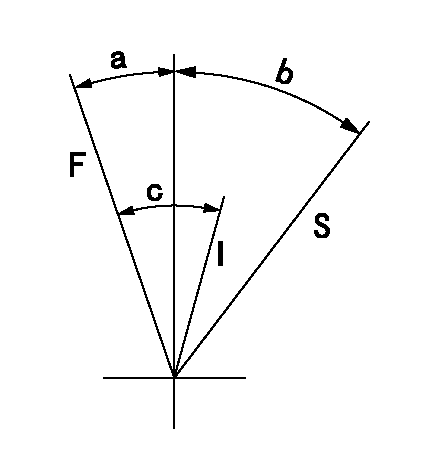
F:Full speed
I:Idle
S:Stop
----------
----------
a=(26deg)+-5deg b=32deg+-3deg c=(26deg)+-5deg
----------
----------
a=(26deg)+-5deg b=32deg+-3deg c=(26deg)+-5deg
Timing setting
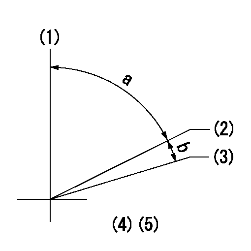
(1)Pump vertical direction
(2)Position of key groove at No 1 cylinder's beginning of injection
(3)Stamp aligning marks on the pump housing flange.
(4)-
(5)-
----------
----------
a=59deg36min+-3deg b=0deg24min+-30min
----------
----------
a=59deg36min+-3deg b=0deg24min+-30min
Information:
Caterpillar Diesel Truck Engines can operate effectively in cold weather. However, engine starting and operation in cold weather is dependent on the type of fuel used, oil viscosity and other optional starting aids. The purpose of this section is to explain potential problems and steps which can be taken to minimize starting and operation problems when the ambient air temperature is colder than 0°C (+32°F) down to -55°C (-67°F).Fuel and the Effect from Cold Weather
Store the fuel outside to allow water (condensation) to freeze after separation from the fuel and to indicate any immediate temperature affect on the fuel.The use of starting aids, engine oil pan heaters, engine coolant heaters, fuel heaters and fuel line insulation also provide a means of minimizing starting and fuel problems in cold weather when No.2 diesel fuel is used.Fuel Related Components in Cold Weather
Fuel Tanks
Fuel tanks should contain some provision for draining water and sediment from the bottom of the tanks. Some fuel tanks use supply pipes that allow water and sediment to settle below the end of the fuel supply pipe. This water and sediment should be drained at each oil change.Some fuel tanks use supply lines that take fuel directly from the bottom of the tank. If equipped with this system, regular maintenance of the fuel system filter(s) is important.Fuel Heaters
Only thermostatically controlled or self-regulating fuel heaters should be used with this engine.
Heat exchanger-type fuel heaters should have a bypass provision to prevent excessive heating of the fuel in warm weather operation. This overheating of the fuel will cause a loss of engine power.Fuel heaters prevent plugging of the fuel filters in cold weather due to waxing. Non-thermostatically controlled fuel heaters can heat the fuel in excess of 65°C (150°F). High fuel temperatures reduce engine performance and power availability.A fuel heater should be installed so that the fuel is heated before it enters the fuel filter. Select a fuel heater that is mechanically simple, yet adequate for the application. The fuel heater should also prevent overheating of the fuel. Choose a fuel heater with as large a heating surface as practical. Small heaters can be too hot in their limited surface area.Disconnect or deactivate the fuel heater in warm weather. A loss of engine power can occur if the fuel supply temperature exceeds 37°C (100°F).For further information on fuel or cylinder block (coolant) heaters, contact Caterpillar.Fuel Filters
The primary fuel filter and/or water separator is installed between the fuel tank and the engine mounted fuel filter. The location of the primary fuel filter is important in cold weather operation. The primary fuel filter and its fuel supply line are the most common components affected by cold fuel.The best location for the primary fuel filter is in the engine compartment, where it will benefit from the radiant heat of the engine. A filter mounted outside the frame rails, or any location exposed to wind, can be a persistent problem in cold weather.Refer to the Parts Manual for this engine to determine the
