Information injection-pump assembly
ZEXEL
101692-3661
1016923661
KOMATSU
6206711310
6206711310
Rating:
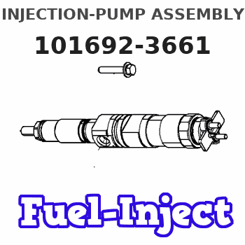
Service parts 101692-3661 INJECTION-PUMP ASSEMBLY:
1.
_
5.
AUTOM. ADVANCE MECHANIS
6.
COUPLING PLATE
7.
COUPLING PLATE
8.
_
9.
_
11.
Nozzle and Holder
12.
Open Pre:MPa(Kqf/cm2)
19.6(200)
15.
NOZZLE SET
Cross reference number
ZEXEL
101692-3661
1016923661
KOMATSU
6206711310
6206711310
Zexel num
Bosch num
Firm num
Name
Calibration Data:
Adjustment conditions
Test oil
1404 Test oil ISO4113 or {SAEJ967d}
1404 Test oil ISO4113 or {SAEJ967d}
Test oil temperature
degC
40
40
45
Nozzle and nozzle holder
105780-8140
Bosch type code
EF8511/9A
Nozzle
105780-0000
Bosch type code
DN12SD12T
Nozzle holder
105780-2080
Bosch type code
EF8511/9
Opening pressure
MPa
17.2
Opening pressure
kgf/cm2
175
Injection pipe
Outer diameter - inner diameter - length (mm) mm 6-2-600
Outer diameter - inner diameter - length (mm) mm 6-2-600
Tester oil delivery pressure
kPa
157
157
157
Tester oil delivery pressure
kgf/cm2
1.6
1.6
1.6
Direction of rotation (viewed from drive side)
Right R
Right R
Injection timing adjustment
Direction of rotation (viewed from drive side)
Right R
Right R
Injection order
1-5-3-6-
2-4
Pre-stroke
mm
3.6
3.55
3.65
Rack position
Point A R=A
Point A R=A
Beginning of injection position
Drive side NO.1
Drive side NO.1
Difference between angles 1
Cal 1-5 deg. 60 59.5 60.5
Cal 1-5 deg. 60 59.5 60.5
Difference between angles 2
Cal 1-3 deg. 120 119.5 120.5
Cal 1-3 deg. 120 119.5 120.5
Difference between angles 3
Cal 1-6 deg. 180 179.5 180.5
Cal 1-6 deg. 180 179.5 180.5
Difference between angles 4
Cyl.1-2 deg. 240 239.5 240.5
Cyl.1-2 deg. 240 239.5 240.5
Difference between angles 5
Cal 1-4 deg. 300 299.5 300.5
Cal 1-4 deg. 300 299.5 300.5
Injection quantity adjustment
Adjusting point
A
Rack position
10.3
Pump speed
r/min
1250
1250
1250
Average injection quantity
mm3/st.
36.7
34.7
38.7
Max. variation between cylinders
%
0
-2.5
2.5
Basic
*
Fixing the lever
*
Injection quantity adjustment_02
Adjusting point
B
Rack position
10.8
Pump speed
r/min
800
800
800
Average injection quantity
mm3/st.
38.6
36.6
40.6
Fixing the lever
*
Injection quantity adjustment_03
Adjusting point
-
Rack position
9.8+-0.5
Pump speed
r/min
400
400
400
Average injection quantity
mm3/st.
8.5
7.5
9.5
Max. variation between cylinders
%
0
-15
15
Fixing the rack
*
Remarks
Adjust only variation between cylinders; adjust governor according to governor specifications.
Adjust only variation between cylinders; adjust governor according to governor specifications.
Test data Ex:
Governor adjustment
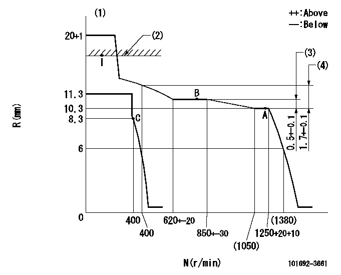
N:Pump speed
R:Rack position (mm)
(1)Notch fixed: K
(2)RACK CAP: R1
(3)Rack difference between N = N1 and N = N2
(4)Rack difference between N = N3 and N = N4
----------
K=20 R1=(17.5)mm N1=1250r/min N2=800r/min N3=1250r/min N4=400r/min
----------
----------
K=20 R1=(17.5)mm N1=1250r/min N2=800r/min N3=1250r/min N4=400r/min
----------
Speed control lever angle
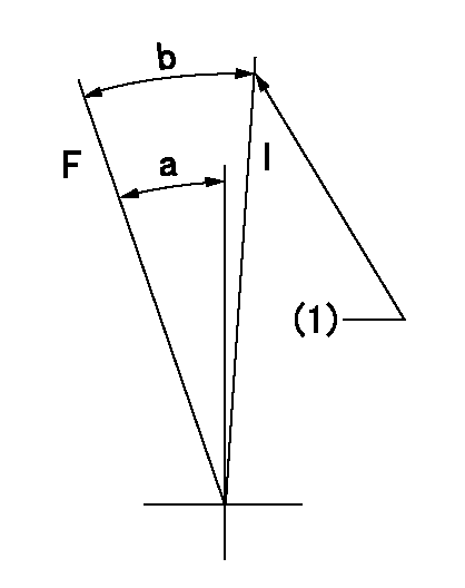
F:Full speed
I:Idle
(1)Stopper bolt setting
----------
----------
a=25deg+-5deg b=28deg+-5deg
----------
----------
a=25deg+-5deg b=28deg+-5deg
Stop lever angle
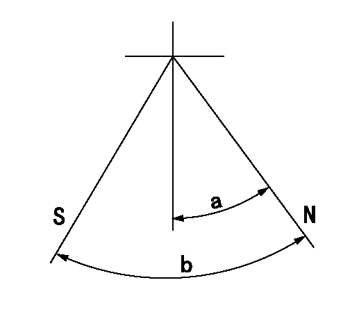
N:Pump normal
S:Stop the pump.
----------
----------
a=26.5deg+-5deg b=53deg+-5deg
----------
----------
a=26.5deg+-5deg b=53deg+-5deg
Timing setting
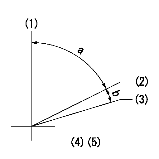
(1)Pump vertical direction
(2)Position of key groove at No 1 cylinder's beginning of injection
(3)Stamp aligning marks on the pump housing flange.
(4)-
(5)-
----------
----------
a=59deg36min+-3deg b=0deg24min+-30min
----------
----------
a=59deg36min+-3deg b=0deg24min+-30min
Information:
Fuel Economy
Fuel is the largest single operating cost of today's on-highway truck engines. Improved fuel economy can have a substantial impact on operating profit. The most significant factors that influence vehicle fuel economy are:* Driver techniques* Vehicle efficiency/Truck Specifications* Operating conditions* Engine efficiencyDriver Techniques
The manner in which a vehicle is driven can have a dramatic effect on fuel consumption. Operators can maximize fuel economy and engine life by practicing the techniques of using minimum power and low engine rpm. The following tips can optimize fuel economy by making maximum use of the potential efficiency of the engine and vehicle.Caterpillar engines are designed to operate at lower engine rpm (speed) and have demonstrated excellent fuel savings and longer service life when operated in this manner.Uphill Operation
Minimize the number of downshifts. Vehicle speed (momentum) is always lost between downshifts. Therefore, unnecessary downshifts waste a portion of that fuel consumed to maintain vehicle speed in the previous gear. Your Caterpillar engine has a very broad usable speed range and excellent torque rise that will provide exceptional hill climbing capability.For best performance when climbing a hill, allow the engine to lug down to peak torque (1560 rpm) speed before downshifting and allow the engine run at a lower speed (down to 1400 rpm) if the truck/vehicle will make the top without another downshift. Fuel economy will be best if you let the engine lug back to around this speed before you downshift. Downshift until a gear is reached in which the engine will pull the load. This technique will also operate the engine through the most fuel efficient speed range.Allowing the engine to lug below peak torque is permissible if the truck/vehicle is cresting the top of a hill without downshifting. However, note that extended operation in a lug condition will raise exhaust temperature and cylinder pressure. This can lead to reduced engine life.
DO NOT allow the engine rpm to exceed 2900 rpm, engine damage can result.
Downhill Operation
When cresting a hill, the decision of whether to use power or not on the downside of the hill must be made. Best fuel economy results from using minimum power to get back to speed after climbing a grade. However, care must be taken not to allow the engine to overspeed.* On a downgrade, do not coast with the clutch disengaged or put the transmission in NEUTRAL. A simple rule to follow is to select the same gear that would be required to go up the hill. However, DO NOT allow the engine to overspeed.* Select the correct gear that does not allow the engine speed (rpm) to exceed the 2900 rpm limit and use the engine retarder and/or service brakes to limit the speed of the truck. Refer to the rated (full load) rpm as shown on the Engine Information Plate.Saving fuel on rolling hills provide a great opportunity to reduce fuel consumption. Avoid downshifting on small hills. If a hill can be topped without downshifting, even if the engine lugs to the peak
