Information injection-pump assembly
ZEXEL
101692-3520
1016923520
Rating:
Cross reference number
ZEXEL
101692-3520
1016923520
Zexel num
Bosch num
Firm num
Name
101692-3520
KOMATSU
INJECTION-PUMP ASSEMBLY
S6D95L *
S6D95L *
Calibration Data:
Adjustment conditions
Test oil
1404 Test oil ISO4113 or {SAEJ967d}
1404 Test oil ISO4113 or {SAEJ967d}
Test oil temperature
degC
40
40
45
Nozzle and nozzle holder
105780-8140
Bosch type code
EF8511/9A
Nozzle
105780-0000
Bosch type code
DN12SD12T
Nozzle holder
105780-2080
Bosch type code
EF8511/9
Opening pressure
MPa
17.2
Opening pressure
kgf/cm2
175
Injection pipe
Outer diameter - inner diameter - length (mm) mm 6-2-600
Outer diameter - inner diameter - length (mm) mm 6-2-600
Tester oil delivery pressure
kPa
157
157
157
Tester oil delivery pressure
kgf/cm2
1.6
1.6
1.6
Direction of rotation (viewed from drive side)
Right R
Right R
Injection timing adjustment
Direction of rotation (viewed from drive side)
Right R
Right R
Injection order
1-5-3-6-
2-4
Pre-stroke
mm
3.6
3.55
3.65
Beginning of injection position
Drive side NO.1
Drive side NO.1
Difference between angles 1
Cal 1-5 deg. 60 59.5 60.5
Cal 1-5 deg. 60 59.5 60.5
Difference between angles 2
Cal 1-3 deg. 120 119.5 120.5
Cal 1-3 deg. 120 119.5 120.5
Difference between angles 3
Cal 1-6 deg. 180 179.5 180.5
Cal 1-6 deg. 180 179.5 180.5
Difference between angles 4
Cyl.1-2 deg. 240 239.5 240.5
Cyl.1-2 deg. 240 239.5 240.5
Difference between angles 5
Cal 1-4 deg. 300 299.5 300.5
Cal 1-4 deg. 300 299.5 300.5
Injection quantity adjustment
Adjusting point
A
Rack position
11.4
Pump speed
r/min
1250
1250
1250
Average injection quantity
mm3/st.
54.7
53.7
55.7
Max. variation between cylinders
%
0
-2.5
2.5
Basic
*
Fixing the lever
*
Injection quantity adjustment_02
Adjusting point
-
Rack position
9.5+-0.5
Pump speed
r/min
450
450
450
Average injection quantity
mm3/st.
12.5
11.5
13.5
Max. variation between cylinders
%
0
-15
15
Fixing the rack
*
Remarks
Adjust only variation between cylinders; adjust governor according to governor specifications.
Adjust only variation between cylinders; adjust governor according to governor specifications.
Test data Ex:
Governor adjustment
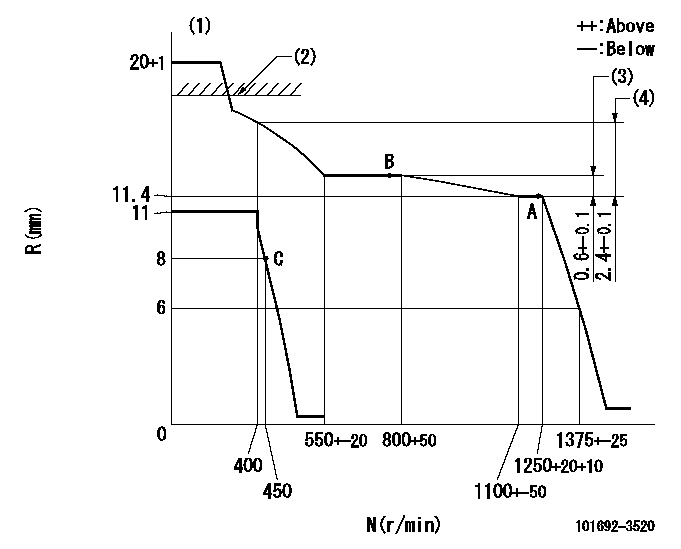
N:Pump speed
R:Rack position (mm)
(1)Target notch: K
(2)RACK CAP: R1
(3)Rack difference between N = N1 and N = N2
(4)Rack difference between N = N3 and N = N4
----------
K=8 R1=(17.5)mm N1=1250r/min N2=800r/min N3=1250r/min N4=400r/min
----------
----------
K=8 R1=(17.5)mm N1=1250r/min N2=800r/min N3=1250r/min N4=400r/min
----------
Speed control lever angle
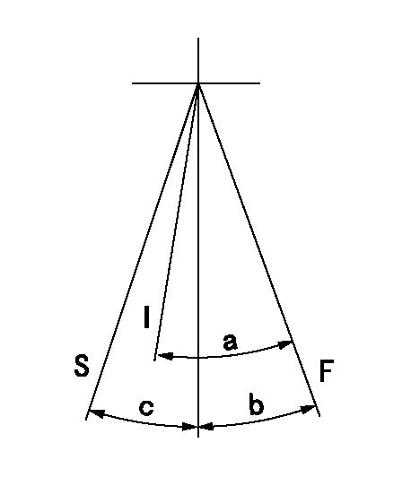
F:Full speed
I:Idle
S:Stop
----------
----------
a=29deg+-5deg b=10deg+-5deg c=32deg+-3deg
----------
----------
a=29deg+-5deg b=10deg+-5deg c=32deg+-3deg
Timing setting

(1)Pump vertical direction
(2)Position of key groove at No 1 cylinder's beginning of injection
(3)Stamp aligning marks on the pump housing flange.
(4)-
(5)-
----------
----------
a=59deg36min+-3deg b=0deg24min+-30min
----------
----------
a=59deg36min+-3deg b=0deg24min+-30min
Information:
Crankcase Breather
Clean
This maintenance is to be performed every other oil change or 600 hours. 1. Loosen hose clamp (1) and remove the hose from the cover.2. Loosen three breather cover bolts (2) and remove cover (3). 3. Remove breather element (4), and wash in clean, nonflammable solvent and allow to dry. 4. Install clean, dry breather element (4).5. Install cover (3) and bolts (2).5. Install hose and clamp (1). Tighten clamp (1) to 27 4.5 lb in (3.0 0.5 N m). Refer to topic Torque Specifications for the proper torque of hose clamp-worm drive band type. If the crankcase breather is not maintained on a regular basis, it will become plugged. A plugged crankcase breather would result in excessive crankcase pressure that may cause crankshaft seal leakage.Refer to the Torque Specifications section of this manual for Torque for Standard Hose Clamps-Worm Drive Band Type hose clamps if your engine is equipped.Alternator, Fan and Accessory Drive Belts
Inspect/Replace
Inspect the condition and adjustment of alternator belts and fan drive belts.Inspect all drive belts for wear and replace if they show any signs of wear.If one belt in a set requires replacement, always install a new matched set of belts. Never replace just the worn belt. If only the worn belt is replaced, the new belt will carry all the load, as it will not be stretched as much as the older belts. All the belts will fail in rapid succession.Belt Adjustment
If belts are too loose, they vibrate enough to cause unnecessary wear on the belts and pulleys.If belts are too tight, unnecessary stresses are placed upon the pulley bearings and belts which might shorten the life of both.The engine is equipped with an automatic belt tensioner, adjustments should not be necessary.To check the belt tension if NOT equipped with an automatic belt tensioner, refer to the vehicle manufacturer's recommendations. Correctly adjusted belts will deflect approximately 3/8 to 5/8 inch (9 to 15 mm).Hoses and Clamps
Inspect
* Inspect all hoses for leaks due to cracking, softness and loose clamps.* Replace hoses that are cracked or soft and tighten loose clamps.Before Replacing Hoses
1. After engine is cool, loosen the radiator filler cap slowly to relieve any pressure and remove the cap.2. Drain the coolant from the cooling system to a level below the hose being replaced.3. Remove the hose clamps, disconnect the old hose and replace with a new hose.4. Install hose clamps. (See the Torque for Standard Hose Clamps-Worm Band Type chart in the Torque Specifications section of this publication for the appropriate torque value.) For constant torque hose clamps, also refer to the Torque Specifications section in this publication.After Replacing Hoses
Refer to Cooling System Specifications in this publication and/or consult your Caterpillar dealer for more detailed specifications.5. Add coolant water mixture to the cooling system. Fill to the proper level by mixing a solution of acceptable water and Caterpillar Antifreeze. Test for supplemental additive (Conditioner) concentration. Add proper amount, or if equipped with a coolant additive element, install the appropriate
Have questions with 101692-3520?
Group cross 101692-3520 ZEXEL
Komatsu
101692-3520
INJECTION-PUMP ASSEMBLY
S6D95L
S6D95L