Information injection-pump assembly
ZEXEL
101692-3510
1016923510
Rating:
Cross reference number
ZEXEL
101692-3510
1016923510
Zexel num
Bosch num
Firm num
Name
101692-3510
KOMATSU
INJECTION-PUMP ASSEMBLY
6D95L *
6D95L *
Calibration Data:
Adjustment conditions
Test oil
1404 Test oil ISO4113 or {SAEJ967d}
1404 Test oil ISO4113 or {SAEJ967d}
Test oil temperature
degC
40
40
45
Nozzle and nozzle holder
105780-8140
Bosch type code
EF8511/9A
Nozzle
105780-0000
Bosch type code
DN12SD12T
Nozzle holder
105780-2080
Bosch type code
EF8511/9
Opening pressure
MPa
17.2
Opening pressure
kgf/cm2
175
Injection pipe
Outer diameter - inner diameter - length (mm) mm 6-2-600
Outer diameter - inner diameter - length (mm) mm 6-2-600
Tester oil delivery pressure
kPa
157
157
157
Tester oil delivery pressure
kgf/cm2
1.6
1.6
1.6
Direction of rotation (viewed from drive side)
Right R
Right R
Injection timing adjustment
Direction of rotation (viewed from drive side)
Right R
Right R
Injection order
1-5-3-6-
2-4
Pre-stroke
mm
3.6
3.55
3.65
Beginning of injection position
Drive side NO.1
Drive side NO.1
Difference between angles 1
Cal 1-5 deg. 60 59.5 60.5
Cal 1-5 deg. 60 59.5 60.5
Difference between angles 2
Cal 1-3 deg. 120 119.5 120.5
Cal 1-3 deg. 120 119.5 120.5
Difference between angles 3
Cal 1-6 deg. 180 179.5 180.5
Cal 1-6 deg. 180 179.5 180.5
Difference between angles 4
Cyl.1-2 deg. 240 239.5 240.5
Cyl.1-2 deg. 240 239.5 240.5
Difference between angles 5
Cal 1-4 deg. 300 299.5 300.5
Cal 1-4 deg. 300 299.5 300.5
Injection quantity adjustment
Adjusting point
A
Rack position
10.3
Pump speed
r/min
1125
1125
1125
Average injection quantity
mm3/st.
37.2
36.2
38.2
Max. variation between cylinders
%
0
-2.5
2.5
Basic
*
Fixing the lever
*
Injection quantity adjustment_02
Adjusting point
-
Rack position
9.7+-0.5
Pump speed
r/min
350
350
350
Average injection quantity
mm3/st.
8
7
9
Max. variation between cylinders
%
0
-15
15
Fixing the rack
*
Remarks
Adjust only variation between cylinders; adjust governor according to governor specifications.
Adjust only variation between cylinders; adjust governor according to governor specifications.
Test data Ex:
Governor adjustment
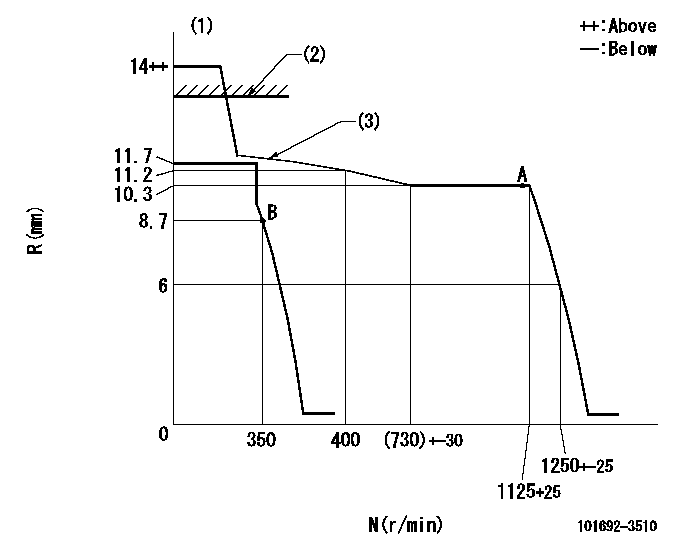
N:Pump speed
R:Rack position (mm)
(1)Target notch: K
(2)RACK CAP: R1
(3)The torque control spring must does not have a set force.
----------
K=16 R1=(13)mm
----------
----------
K=16 R1=(13)mm
----------
Speed control lever angle

F:Full speed
I:Idle
(1)Stopper bolt setting
----------
----------
a=18deg+-5deg b=29deg+-5deg
----------
----------
a=18deg+-5deg b=29deg+-5deg
Stop lever angle

N:Pump normal
S:Stop the pump.
----------
----------
a=26.5deg+-5deg b=53deg+-5deg
----------
----------
a=26.5deg+-5deg b=53deg+-5deg
Timing setting

(1)Pump vertical direction
(2)Position of key groove at No 1 cylinder's beginning of injection
(3)Stamp aligning marks on the pump housing flange.
(4)-
(5)-
----------
----------
a=59deg36min+-3deg b=0deg24min+-30min
----------
----------
a=59deg36min+-3deg b=0deg24min+-30min
Information:
Check Air Cleaner Service Indicator
Typical air cleaner indicator shown.Your engine may be equipped with a different indicator.A service indicator (if equipped) may be mounted on your dashboard or in the engine compartment. A colored piston showing in the window indicates the need for servicing the air cleaner.Observe the air cleaner service indicator. Clean or replace the air cleaner element when the yellow diaphragm enters the red zone, the red piston locks in the visible position or 25 inches (635 mm) H2O.As the air cleaner element becomes plugged, the difference of air pressure between the inlet side (dirty side) and the engine side (clean side) will increase.If your air cleaner element becomes plugged, the air can split the element filter material. Unfiltered air will drastically accelerate internal engine wear.Your Caterpillar dealer has air filter elements to service most popular makes of trucks. Contact your Caterpillar dealer for the correct filter element to fit your truck.Cleaning Caterpillar Air Cleaner Elements
The Caterpillar air filter element can be cleaned several times before replacement. The element, when cleaned, should be thoroughly checked for rips or tears in the filter material. Replace the primary element at least every year even though it has been cleaned less than the maximum recommendation.Refer to Guideline for Reusable Parts-Procedures to Inspect and Clean Air Filters, form SEBF8062 for information on inspecting, cleaning and reusing Caterpillar air filter elements.
Clean or replace elements at intervals recommended by the air cleaner OEM or truck manufacturer's recommendations and operating (dust, dirt and debris) conditions, or when required by the restriction indicator.Never service the air cleaner with the engine running since this will allow dirt to enter the engine.
Check the precleaner (if equipped) daily for accumulation of dirt and debris. Remove any dirt and debris as needed.Remove and Install Air Cleaner Elements
1. Loosen the retaining bolts and remove the end cover on the air cleaner housing.2. Remove and inspect the element for damaged pleats, gaskets or seals. Replace the element if damaged.3. Clean the inside of the housing.4. Replace the element in the housing.5. Install the end cover on the housing.6. Reset the service indicator by pushing the piston plunger in.Inspecting Element
7. Insert a light inside of the clean, dry element. Inspect it for rips and tears. Discard the element if damaged.8. Wrap and store good elements in a clean, dry place.
Have questions with 101692-3510?
Group cross 101692-3510 ZEXEL
Komatsu
101692-3510
INJECTION-PUMP ASSEMBLY
6D95L
6D95L