Information injection-pump assembly
ZEXEL
101692-3491
1016923491
KOMATSU
6207711333
6207711333
Rating:
Cross reference number
ZEXEL
101692-3491
1016923491
KOMATSU
6207711333
6207711333
Zexel num
Bosch num
Firm num
Name
101692-3491
6207711333 KOMATSU
INJECTION-PUMP ASSEMBLY
S6D95L * K
S6D95L * K
Calibration Data:
Adjustment conditions
Test oil
1404 Test oil ISO4113 or {SAEJ967d}
1404 Test oil ISO4113 or {SAEJ967d}
Test oil temperature
degC
40
40
45
Nozzle and nozzle holder
105780-8140
Bosch type code
EF8511/9A
Nozzle
105780-0000
Bosch type code
DN12SD12T
Nozzle holder
105780-2080
Bosch type code
EF8511/9
Opening pressure
MPa
17.2
Opening pressure
kgf/cm2
175
Injection pipe
Outer diameter - inner diameter - length (mm) mm 6-2-600
Outer diameter - inner diameter - length (mm) mm 6-2-600
Tester oil delivery pressure
kPa
157
157
157
Tester oil delivery pressure
kgf/cm2
1.6
1.6
1.6
Direction of rotation (viewed from drive side)
Right R
Right R
Injection timing adjustment
Direction of rotation (viewed from drive side)
Right R
Right R
Injection order
1-5-3-6-
2-4
Pre-stroke
mm
3.6
3.55
3.65
Beginning of injection position
Drive side NO.1
Drive side NO.1
Difference between angles 1
Cal 1-5 deg. 60 59.5 60.5
Cal 1-5 deg. 60 59.5 60.5
Difference between angles 2
Cal 1-3 deg. 120 119.5 120.5
Cal 1-3 deg. 120 119.5 120.5
Difference between angles 3
Cal 1-6 deg. 180 179.5 180.5
Cal 1-6 deg. 180 179.5 180.5
Difference between angles 4
Cyl.1-2 deg. 240 239.5 240.5
Cyl.1-2 deg. 240 239.5 240.5
Difference between angles 5
Cal 1-4 deg. 300 299.5 300.5
Cal 1-4 deg. 300 299.5 300.5
Injection quantity adjustment
Adjusting point
A
Rack position
10.1
Pump speed
r/min
1200
1200
1200
Average injection quantity
mm3/st.
36.6
35.6
37.6
Max. variation between cylinders
%
0
-2.5
2.5
Basic
*
Fixing the lever
*
Injection quantity adjustment_02
Adjusting point
-
Rack position
10.9+-0.
5
Pump speed
r/min
350
350
350
Average injection quantity
mm3/st.
12.5
11.5
13.5
Max. variation between cylinders
%
0
-15
15
Fixing the rack
*
Remarks
Adjust only variation between cylinders; adjust governor according to governor specifications.
Adjust only variation between cylinders; adjust governor according to governor specifications.
Test data Ex:
Governor adjustment
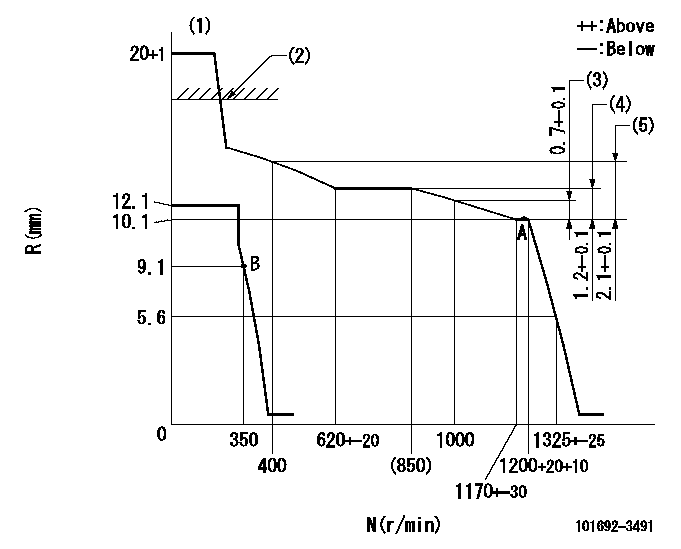
N:Pump speed
R:Rack position (mm)
(1)Target notch: K
(2)RACK LIMIT: RAL
(3)Rack difference between N = N1 and N = N2
(4)Rack difference between N = N3 and N = N4
(5)Rack difference between N = N5 and N = N6.
----------
K=14 RAL=15+0.2mm N1=1200r/min N2=1000r/min N3=1200r/min N4=800r/min N5=1200r/min N6=400r/min
----------
----------
K=14 RAL=15+0.2mm N1=1200r/min N2=1000r/min N3=1200r/min N4=800r/min N5=1200r/min N6=400r/min
----------
Speed control lever angle

F:Full speed
I:Idle
(1)Stopper bolt setting
----------
----------
a=19deg+-5deg b=26deg+-5deg
----------
----------
a=19deg+-5deg b=26deg+-5deg
Stop lever angle

N:Pump normal
S:Stop the pump.
----------
----------
a=26.5deg+-5deg b=53deg+-5deg
----------
----------
a=26.5deg+-5deg b=53deg+-5deg
Timing setting

(1)Pump vertical direction
(2)Position of key groove at No 1 cylinder's beginning of injection
(3)Stamp aligning marks on the pump housing flange.
(4)-
(5)-
----------
----------
a=59deg36min+-3deg b=0deg24min+-30min
----------
----------
a=59deg36min+-3deg b=0deg24min+-30min
Information:
You must read and understand the warnings and instructions contained in the Safety section of this manual before performing any operation or maintenance procedures.Walk-Around Inspection
Inspect Engine for Leaks and Loose Connections
For maximum service life of your truck engine, make a thorough under the hood inspection before starting the engine. Look for such items as oil or coolant leaks, loose bolts, worn fan belts, loose connections and trash build-up. Remove trash build-up and have repairs made as needed.Check the fluid levels more frequently than the recommended maintenance intervals and continue to monitor fluid levels until any leak is found and fixed.* Wipe all fittings, caps and plugs before performing maintenance to reduce the chance of system contamination. Inspect:* Radiator and ATAAC core for leaks and trash build-up.* Radiator and ATAAC air intake system hoses and elbows for cracks and loose clamps.* Fan and accessory drive belts for cracks, breaks or other damage.Belts for multiple groove pulleys must be replaced as matched sets. If only one belt of a two or three belt set is replaced, it will carry more of a load than the belts not replaced since the older belts are stretched. The additional load on the new belt could cause it to break. Inspect:* Water pump for coolant leaks. The water pump seal is lubricated by coolant in the cooling system. It is normal for a small amount of leakage to occur as the engine cools down and parts contract. If leaks are found, check the coolant level frequently and continue to monitor the level until the water pump is repaired. Excessive coolant leakage may indicate the need to replace the water pump seal.For removal and installation of water pumps and/or seals, see the Service Manual for this engine or consult your Caterpillar dealer. Inspect:* Lube system for leaks, such as front and rear crankshaft seals, oil pan, oil filters and valve covers.* Fuel system for leaks, loose fuel line clamps and fittings and loose or worn hoses.
Fuel line clamps should not be over torqued. Over torqueing causes the clamps to butterfly, which results in low clamping force and fuel line vibration and eventual failure.
Tighten fuel line clamps as required using 6V4980 Torque Screwdriver Tool Group. The standard torque for these fasteners (#10 screw) is 20 lb inch (2.26 N m).* Inspect wiring and wiring harnesses for loose connections and worn or frayed wires. Inspect:* Air intake system hoses and elbows for cracks and loose clamps. * ECM to cylinder head ground strap and starter negative cable for good connection and condition.All guards must be in place. Repair or replace missing or damaged guards.Check condition of batteries and the level of electrolyte, unless equipped with a maintenance free battery.Refer to OEM truck owner manual or manufacturers' recommendations for battery maintenance.
Have questions with 101692-3491?
Group cross 101692-3491 ZEXEL
Komatsu
Komatsu
Komatsu
101692-3491
6207711333
INJECTION-PUMP ASSEMBLY
S6D95L
S6D95L