Information injection-pump assembly
ZEXEL
101692-3481
1016923481
Rating:
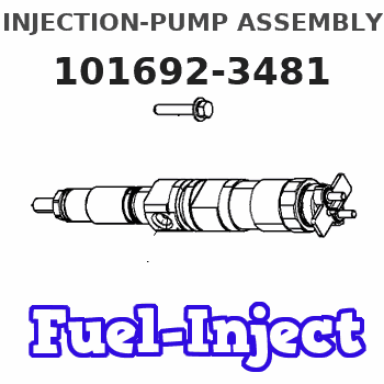
Service parts 101692-3481 INJECTION-PUMP ASSEMBLY:
1.
_
5.
AUTOM. ADVANCE MECHANIS
6.
COUPLING PLATE
7.
COUPLING PLATE
8.
_
9.
_
11.
Nozzle and Holder
6207-11-3100
12.
Open Pre:MPa(Kqf/cm2)
19.6{200}
15.
NOZZLE SET
Cross reference number
ZEXEL
101692-3481
1016923481
Zexel num
Bosch num
Firm num
Name
101692-3481
INJECTION-PUMP ASSEMBLY
Calibration Data:
Adjustment conditions
Test oil
1404 Test oil ISO4113 or {SAEJ967d}
1404 Test oil ISO4113 or {SAEJ967d}
Test oil temperature
degC
40
40
45
Nozzle and nozzle holder
105780-8140
Bosch type code
EF8511/9A
Nozzle
105780-0000
Bosch type code
DN12SD12T
Nozzle holder
105780-2080
Bosch type code
EF8511/9
Opening pressure
MPa
17.2
Opening pressure
kgf/cm2
175
Injection pipe
Outer diameter - inner diameter - length (mm) mm 6-2-600
Outer diameter - inner diameter - length (mm) mm 6-2-600
Tester oil delivery pressure
kPa
157
157
157
Tester oil delivery pressure
kgf/cm2
1.6
1.6
1.6
Direction of rotation (viewed from drive side)
Right R
Right R
Injection timing adjustment
Direction of rotation (viewed from drive side)
Right R
Right R
Injection order
1-5-3-6-
2-4
Pre-stroke
mm
3.6
3.55
3.65
Rack position
Point A R=A
Point A R=A
Beginning of injection position
Drive side NO.1
Drive side NO.1
Difference between angles 1
Cal 1-5 deg. 60 59.5 60.5
Cal 1-5 deg. 60 59.5 60.5
Difference between angles 2
Cal 1-3 deg. 120 119.5 120.5
Cal 1-3 deg. 120 119.5 120.5
Difference between angles 3
Cal 1-6 deg. 180 179.5 180.5
Cal 1-6 deg. 180 179.5 180.5
Difference between angles 4
Cyl.1-2 deg. 240 239.5 240.5
Cyl.1-2 deg. 240 239.5 240.5
Difference between angles 5
Cal 1-4 deg. 300 299.5 300.5
Cal 1-4 deg. 300 299.5 300.5
Injection quantity adjustment
Adjusting point
A
Rack position
9.2
Pump speed
r/min
1200
1200
1200
Average injection quantity
mm3/st.
26.2
25.2
27.2
Max. variation between cylinders
%
0
-2.5
2.5
Basic
*
Fixing the lever
*
Injection quantity adjustment_02
Adjusting point
-
Rack position
10.7+-0.
5
Pump speed
r/min
350
350
350
Average injection quantity
mm3/st.
10.5
9.5
11.5
Max. variation between cylinders
%
0
-15
15
Fixing the rack
*
Remarks
Adjust only variation between cylinders; adjust governor according to governor specifications.
Adjust only variation between cylinders; adjust governor according to governor specifications.
Test data Ex:
Governor adjustment
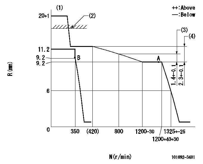
N:Pump speed
R:Rack position (mm)
(1)Target notch: K
(2)RACK CAP: R1
(3)Rack difference between N = N1 and N = N2
(4)Rack difference between N = N3 and N = N4
----------
K=16 R1=(17.5)mm N1=1200r/min N2=800r/min N3=1200r/min N4=350r/min
----------
----------
K=16 R1=(17.5)mm N1=1200r/min N2=800r/min N3=1200r/min N4=350r/min
----------
Speed control lever angle

F:Full speed
I:Idle
(1)Stopper bolt setting
----------
----------
a=24deg+-5deg b=27deg+-5deg
----------
----------
a=24deg+-5deg b=27deg+-5deg
Stop lever angle
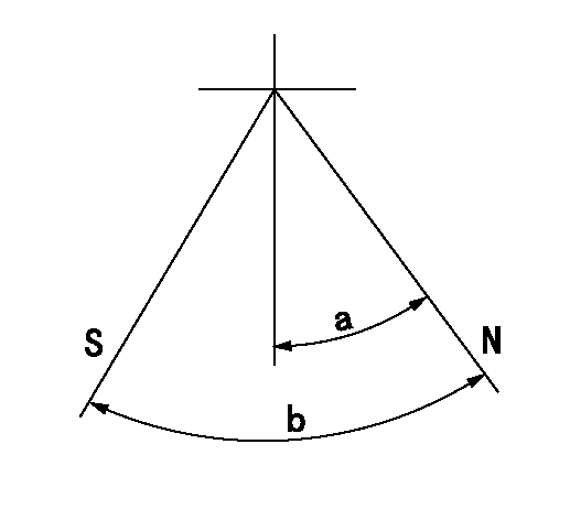
N:Pump normal
S:Stop the pump.
----------
----------
a=26.5deg+-5deg b=53deg+-5deg
----------
----------
a=26.5deg+-5deg b=53deg+-5deg
Timing setting
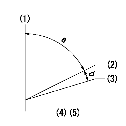
(1)Pump vertical direction
(2)Position of key groove at No 1 cylinder's beginning of injection
(3)Stamp aligning marks on the pump housing flange.
(4)-
(5)-
----------
----------
a=59deg36min+-3deg b=0deg24min+-30min
----------
----------
a=59deg36min+-3deg b=0deg24min+-30min
Information:
Exhaust brakes should not be used as a primary or service brake.
Auxiliary engine braking devices are approved for use on the 3176 Engine.Compression Brake
Operation (Jacobs Brake)
Compression brakes should not be used as a primary or service brake.Do not allow the engine to exceed 2300 rpm. However, engines equipped with a compression brake should not normally be operated above 2100 rpm.
The compression brake is an engine attachment that converts a diesel engine into an air compressor. Its function is to slow the vehicle and reduce brake wear.Operating Controls-Compression Brake
The compression brake controls may include a dash mounted module or an ON/OFF switch and a three position switch with "LO," "MED" and "HI" depending on how many cylinders of braking desired. Refer to the OEM vehicle manual for the type of operating controls that your vehicle is equipped with.Some applications are equipped with a multi-position switch to provide variable retarding capability. Operators should become familiar with the controls on their vehicles.The 3176 ECM monitors the clutch, brake, throttle position and engine rpm to determine when the compression brake can operate. It may take up to two seconds before compression brake activates.Since the compression brake is most effective at rated engine speed, gear selection is very important. Gearing down the vehicle, within the limits of rated engine speed, makes the engine brake a more effective retarder. Maximum retarding occurs at higher engine speeds.However, a compression brake equipped engine should not be operated above 2100 rpm.Cruise Control (If Equipped) OFF
With the Cruise Control (CC) in the OFF position the compression brake will function like any vehicle and engine that is not equipped with Cruise Control (CC).Cruise Control (If Equipped) ON
The driver must apply the service brake approximately two seconds and then release the service brake pedal. If the retarder "LATCH" mode has been programmed, the retarder will continue to slow the vehicle. To release or deactivate the retarder, the clutch or throttle foot pedal must be depressed or the engine rpm drop to 950 rpm.When using "COAST" mode, the compression brake should activate within two seconds after the brake pedal is applied and remain on as long as the brake pedal is applied. At the time the brake pedal is applied, the Cruise Control (CC) will deactivate.For information on adjustment to compression brake slave piston lash, refer to the Maintenance Schedule for Engine Valve Lash.Refer to the Truck Engine Application and Installation Guide, LEBT8121 April, 1988 for more information. Refer to the Systems Operation Test and Adjust in the Service Manual or to Jacobs Brake Troubleshooting Manual, SENR4251 for information regarding this auxiliary braking system.
Have questions with 101692-3481?
Group cross 101692-3481 ZEXEL
Komatsu
101692-3481
INJECTION-PUMP ASSEMBLY
