Information injection-pump assembly
ZEXEL
101692-3460
1016923460
Rating:
Cross reference number
ZEXEL
101692-3460
1016923460
Zexel num
Bosch num
Firm num
Name
Calibration Data:
Adjustment conditions
Test oil
1404 Test oil ISO4113 or {SAEJ967d}
1404 Test oil ISO4113 or {SAEJ967d}
Test oil temperature
degC
40
40
45
Nozzle and nozzle holder
105780-8140
Bosch type code
EF8511/9A
Nozzle
105780-0000
Bosch type code
DN12SD12T
Nozzle holder
105780-2080
Bosch type code
EF8511/9
Opening pressure
MPa
17.2
Opening pressure
kgf/cm2
175
Injection pipe
Outer diameter - inner diameter - length (mm) mm 6-2-600
Outer diameter - inner diameter - length (mm) mm 6-2-600
Tester oil delivery pressure
kPa
157
157
157
Tester oil delivery pressure
kgf/cm2
1.6
1.6
1.6
Direction of rotation (viewed from drive side)
Right R
Right R
Injection timing adjustment
Direction of rotation (viewed from drive side)
Right R
Right R
Injection order
1-5-3-6-
2-4
Pre-stroke
mm
3.6
3.55
3.65
Rack position
Point A R=A
Point A R=A
Beginning of injection position
Drive side NO.1
Drive side NO.1
Difference between angles 1
Cal 1-5 deg. 60 59.5 60.5
Cal 1-5 deg. 60 59.5 60.5
Difference between angles 2
Cal 1-3 deg. 120 119.5 120.5
Cal 1-3 deg. 120 119.5 120.5
Difference between angles 3
Cal 1-6 deg. 180 179.5 180.5
Cal 1-6 deg. 180 179.5 180.5
Difference between angles 4
Cyl.1-2 deg. 240 239.5 240.5
Cyl.1-2 deg. 240 239.5 240.5
Difference between angles 5
Cal 1-4 deg. 300 299.5 300.5
Cal 1-4 deg. 300 299.5 300.5
Injection quantity adjustment
Adjusting point
A
Rack position
11
Pump speed
r/min
1250
1250
1250
Average injection quantity
mm3/st.
45.7
44.7
46.7
Max. variation between cylinders
%
0
-2.5
2.5
Basic
*
Fixing the lever
*
Injection quantity adjustment_02
Adjusting point
-
Rack position
10.5+-0.
5
Pump speed
r/min
400
400
400
Average injection quantity
mm3/st.
12.5
11.5
13.5
Max. variation between cylinders
%
0
-15
15
Fixing the rack
*
Remarks
Adjust only variation between cylinders; adjust governor according to governor specifications.
Adjust only variation between cylinders; adjust governor according to governor specifications.
Test data Ex:
Governor adjustment
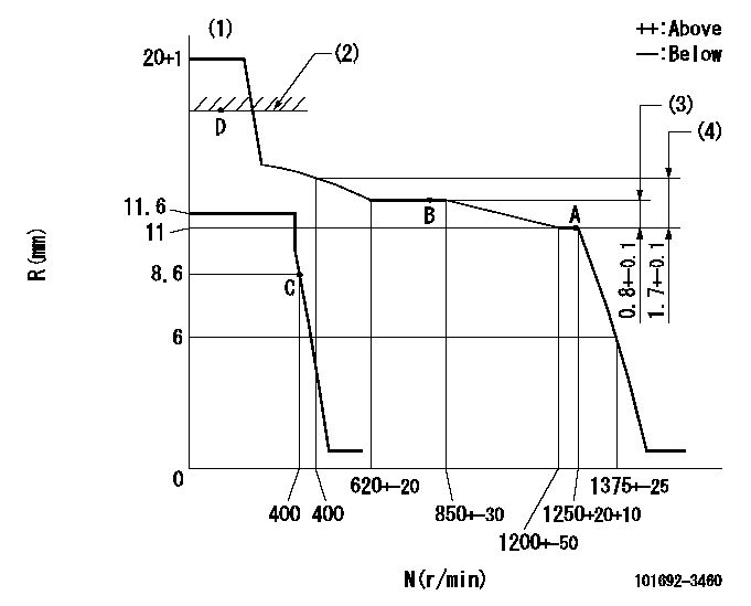
N:Pump speed
R:Rack position (mm)
(1)Target notch: K
(2)RACK CAP: R1
(3)Rack difference between N = N1 and N = N2
(4)Rack difference between N = N3 and N = N4
----------
K=13 R1=(17.5)mm N1=1250r/min N2=800r/min N3=1250r/min N4=400r/min
----------
----------
K=13 R1=(17.5)mm N1=1250r/min N2=800r/min N3=1250r/min N4=400r/min
----------
Speed control lever angle

F:Full speed
I:Idle
(1)Stopper bolt setting
----------
----------
a=15deg+-5deg b=27deg+-5deg
----------
----------
a=15deg+-5deg b=27deg+-5deg
Stop lever angle

N:Pump normal
S:Stop the pump.
----------
----------
a=26.5deg+-5deg b=53deg+-5deg
----------
----------
a=26.5deg+-5deg b=53deg+-5deg
Timing setting

(1)Pump vertical direction
(2)Position of key groove at No 1 cylinder's beginning of injection
(3)Stamp aligning marks on the pump housing flange.
(4)-
(5)-
----------
----------
a=59deg36min+-3deg b=0deg24min+-30min
----------
----------
a=59deg36min+-3deg b=0deg24min+-30min
Information:
PTO Mode Speed Limit (PTO)- Maximum vehicle speed at which the PTO Governor will function (between 0 and 15 mph [0 and 24 km/h]). If vehicle speed signal exceeds the programmed value, the control will exit the PTO Mode. PTO Mode RPM Limit (PTO RPM)- Maximum engine rpm attainable in the PTO Mode. The rpm limits are between 600 and 2300 rpm. PTO Engine Speed Ramp Rate- Engine rpm (speed) rate of increase. This parameter determines ACCEL, DECEL and RESUME PTO Engine rates of increase/decrease. The programmable limits are between 50 rpm/second and 500 rpm/second. Low Gears #1 RPM Limit (LoGr #1)- Engine speed is limited below Low Gear #1 Turn Off Speed. The engine will hesitate at this speed then allow slow acceleration up to Top Engine Limit (TEL). This is to encourage shifting to the next higher gear. The limits are between 1100 and 2300 rpm. Low Gears #1 Turn Off (Lo Gr Off)- The vehicle speed at which LoGr #1 RPM Limit is no longer in effect (turns off between 3 and 30 mph [5 and 48 km/h]). This parameter must be matched with Low Gear #1 RPM Limit to the specific drive train for best performance. Low Gears #2 RPM Limit (LoGr #2)- Similar to Low Gears #1 RPM Limit and typically programmed at a slightly higher rpm. The limits are between 1100 and 2300 rpm. Low Gears #2 Turn Off (LoGr TO)- Similar to Low Gears #1 Turn Off and typically programmed at a slightly higher rpm. The limits are between 5 and 50 mph [8 and 80 km/h]). High Gears RPM Limit (HiGr RPM)- The rpm limit when the vehicle speed is above High Gear Turn On Speed. This is a "hard" limit; the engine will not power above this limit to encourage shifting up into overdrive or top gear. The limits are between 1300 and 2300 rpm. High Gear Turn On Speed (HiGr On)- Vehicle speed where High Gear RPM Limit turns on. This parameter must be matched to the specific drive train for best performance. The limits are between 30 and 127 mph (48 and 204 km/h). Top Engine Limit (TEL)- Maximum allowable engine rpm when the engine is under load. The engine will still achieve Rated rpm (speed) under no load conditions. This parameter is dependent upon Rating Number, with some Rating Numbers allowing no or little variation. The limits are between 1600 and 3000 rpm. Low Engine Idle rpm- Minimum programmed engine rpm (between 600 and 750 rpm). Vehicle Speed Limit- Top vehicle speed the ECM will permit. The ECM will shut off fuel above this speed. The limits are between 30 and 127 mph (48 and 204 km/h and/or gear limit of vehicle. Engine RPM at Vehicle Speed Limit (Eng RPM at VSL)- The maximum rpm that the engine will operate when the vehicle speed signal reaches VSL, or when the ECM detects a vehicle speed signal problem (the ECM will limit engine to this rpm