Information injection-pump assembly
ZEXEL
101692-3410
1016923410
KOMATSU
6207711350
6207711350
Rating:
Cross reference number
ZEXEL
101692-3410
1016923410
KOMATSU
6207711350
6207711350
Zexel num
Bosch num
Firm num
Name
101692-3410
6207711350 KOMATSU
INJECTION-PUMP ASSEMBLY
S6D95L *
S6D95L *
Calibration Data:
Adjustment conditions
Test oil
1404 Test oil ISO4113 or {SAEJ967d}
1404 Test oil ISO4113 or {SAEJ967d}
Test oil temperature
degC
40
40
45
Nozzle and nozzle holder
105780-8140
Bosch type code
EF8511/9A
Nozzle
105780-0000
Bosch type code
DN12SD12T
Nozzle holder
105780-2080
Bosch type code
EF8511/9
Opening pressure
MPa
17.2
Opening pressure
kgf/cm2
175
Injection pipe
Outer diameter - inner diameter - length (mm) mm 6-2-600
Outer diameter - inner diameter - length (mm) mm 6-2-600
Tester oil delivery pressure
kPa
157
157
157
Tester oil delivery pressure
kgf/cm2
1.6
1.6
1.6
Direction of rotation (viewed from drive side)
Right R
Right R
Injection timing adjustment
Direction of rotation (viewed from drive side)
Right R
Right R
Injection order
1-5-3-6-
2-4
Pre-stroke
mm
3.6
3.55
3.65
Rack position
Point A R=A
Point A R=A
Beginning of injection position
Drive side NO.1
Drive side NO.1
Difference between angles 1
Cal 1-5 deg. 60 59.5 60.5
Cal 1-5 deg. 60 59.5 60.5
Difference between angles 2
Cal 1-3 deg. 120 119.5 120.5
Cal 1-3 deg. 120 119.5 120.5
Difference between angles 3
Cal 1-6 deg. 180 179.5 180.5
Cal 1-6 deg. 180 179.5 180.5
Difference between angles 4
Cyl.1-2 deg. 240 239.5 240.5
Cyl.1-2 deg. 240 239.5 240.5
Difference between angles 5
Cal 1-4 deg. 300 299.5 300.5
Cal 1-4 deg. 300 299.5 300.5
Injection quantity adjustment
Adjusting point
A
Rack position
10.8
Pump speed
r/min
1200
1200
1200
Average injection quantity
mm3/st.
43.4
42.4
44.4
Max. variation between cylinders
%
0
-2.5
2.5
Basic
*
Fixing the lever
*
Injection quantity adjustment_02
Adjusting point
-
Rack position
10.5+-0.
5
Pump speed
r/min
400
400
400
Average injection quantity
mm3/st.
12.5
11.5
13.5
Max. variation between cylinders
%
0
-15
15
Fixing the rack
*
Remarks
Adjust only variation between cylinders; adjust governor according to governor specifications.
Adjust only variation between cylinders; adjust governor according to governor specifications.
Test data Ex:
Governor adjustment
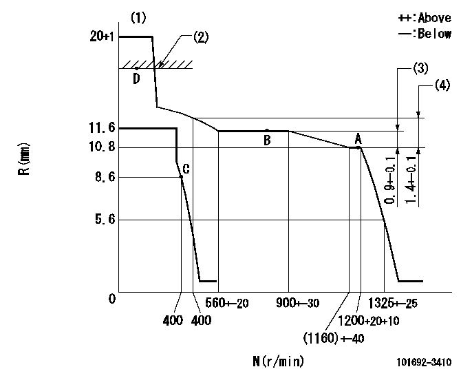
N:Pump speed
R:Rack position (mm)
(1)Target notch: K
(2)RACK CAP: R1
(3)Rack difference between N = N1 and N = N2
(4)Rack difference between N = N3 and N = N4
----------
K=8 R1=(17.5)mm N1=1200r/min N2=800r/min N3=1200r/min N4=400r/min
----------
----------
K=8 R1=(17.5)mm N1=1200r/min N2=800r/min N3=1200r/min N4=400r/min
----------
Speed control lever angle

F:Full speed
I:Idle
S:Stop
----------
----------
a=11deg+-5deg b=32deg+-3deg c=25deg+-5deg
----------
----------
a=11deg+-5deg b=32deg+-3deg c=25deg+-5deg
0000001501 LEVER
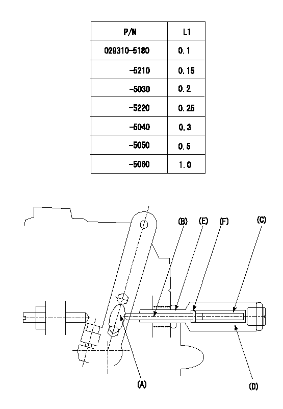
(F) P/N: Part number of the shim
L1:Thickness (mm)
1. Adjustment of the control lever
(1)Perform idling with the control lever (A) contacting the pushrod (B). At this time, confirm that the spring (C) is not compressed by control lever (A)'s operating torque.
(2)To set the stop position, compress spring (C) using the control lever (A) and adjust the rack so that it contacts the guide screw (D) at position L2. Then, set and fix using the lock nut (E). Adjust the rack position L2 at this time using the shim (F).
(3)Confirm that the control lever (A) returns to the idling position when pulled in the stop direction and then released.
----------
L2=0.2~2mm
----------
----------
L2=0.2~2mm
----------
Timing setting

(1)Pump vertical direction
(2)Position of key groove at No 1 cylinder's beginning of injection
(3)Stamp aligning marks on the pump housing flange.
(4)-
(5)-
----------
----------
a=59deg36min+-3deg b=0deg24min+-30min
----------
----------
a=59deg36min+-3deg b=0deg24min+-30min
Information:
Engine Lifting
When it is necessary to remove a component on an angle, remember that the capacity of an eyebolt is less as the angle between the supporting members and the object becomes less than 90°. Eyebolts and brackets should never be bent and should only be loaded in tension.
Use a hoist to remove heavy components. Lift the engine by using an adjustable lifting beam. All supporting members (chains and cables) should be parallel to each other, and as near perpendicular as possible to the top of the object being lifted.Some removals require the use of lifting fixtures to obtain proper balance and to provide safe handling. To remove the engine, use the two lifting eyes on the engine.Lifting eyes are designed for the arrangement as sold. Alterations to lifting eyes and/or arrangement weight make the lifting devices obsolete.If you make alterations, you are responsible for providing adequate lifting devices.Engine Storage
If the engine will not be or has not been started for several weeks, the lubricating oil will drain from the cylinder walls and piston rings.If an engine remains out of service and its use is not immediately planned, special precautions should be taken. Rust can form on the cylinder liner surface, which will increase engine wear and may result in shorter engine life.To prevent this problem from becoming excessive, be sure all lubrication recommendations mentioned in the Maintenance Schedule are completed.If freezing temperatures are expected, check the cooling system for adequate protection against freezing. A 50/50 solution of Caterpillar (permanent-type) Antifreeze and approved water will give protection to -20°F (-29°C).If it will be impossible to start the engine periodically, consult your Caterpillar dealer for instructions to prepare your engine for longer storage periods.Refer to Storage Procedures For Caterpillar Products, form SEHS9031 for more detailed information on engine storage.
Have questions with 101692-3410?
Group cross 101692-3410 ZEXEL
Komatsu
101692-3410
6207711350
INJECTION-PUMP ASSEMBLY
S6D95L
S6D95L