Information injection-pump assembly
ZEXEL
101692-3401
1016923401
KOMATSU
6206711510
6206711510
Rating:
Cross reference number
ZEXEL
101692-3401
1016923401
KOMATSU
6206711510
6206711510
Zexel num
Bosch num
Firm num
Name
Calibration Data:
Adjustment conditions
Test oil
1404 Test oil ISO4113 or {SAEJ967d}
1404 Test oil ISO4113 or {SAEJ967d}
Test oil temperature
degC
40
40
45
Nozzle and nozzle holder
105780-8140
Bosch type code
EF8511/9A
Nozzle
105780-0000
Bosch type code
DN12SD12T
Nozzle holder
105780-2080
Bosch type code
EF8511/9
Opening pressure
MPa
17.2
Opening pressure
kgf/cm2
175
Injection pipe
Outer diameter - inner diameter - length (mm) mm 6-2-600
Outer diameter - inner diameter - length (mm) mm 6-2-600
Tester oil delivery pressure
kPa
157
157
157
Tester oil delivery pressure
kgf/cm2
1.6
1.6
1.6
Direction of rotation (viewed from drive side)
Right R
Right R
Injection timing adjustment
Direction of rotation (viewed from drive side)
Right R
Right R
Injection order
1-5-3-6-
2-4
Pre-stroke
mm
3.6
3.55
3.65
Rack position
Point A R=A
Point A R=A
Beginning of injection position
Drive side NO.1
Drive side NO.1
Difference between angles 1
Cal 1-5 deg. 60 59.5 60.5
Cal 1-5 deg. 60 59.5 60.5
Difference between angles 2
Cal 1-3 deg. 120 119.5 120.5
Cal 1-3 deg. 120 119.5 120.5
Difference between angles 3
Cal 1-6 deg. 180 179.5 180.5
Cal 1-6 deg. 180 179.5 180.5
Difference between angles 4
Cyl.1-2 deg. 240 239.5 240.5
Cyl.1-2 deg. 240 239.5 240.5
Difference between angles 5
Cal 1-4 deg. 300 299.5 300.5
Cal 1-4 deg. 300 299.5 300.5
Injection quantity adjustment
Adjusting point
A
Rack position
R1(9.9)
Pump speed
r/min
1200
1200
1200
Average injection quantity
mm3/st.
31.9
30.9
32.9
Max. variation between cylinders
%
0
-2.5
2.5
Basic
*
Fixing the lever
P
Injection quantity adjustment_02
Adjusting point
-
Rack position
10.5+-0.
5
Pump speed
r/min
400
400
400
Average injection quantity
mm3/st.
10.5
9.5
11.5
Max. variation between cylinders
%
0
-15
15
Fixing the rack
*
Remarks
Adjust only variation between cylinders; adjust governor according to governor specifications.
Adjust only variation between cylinders; adjust governor according to governor specifications.
Test data Ex:
Governor adjustment
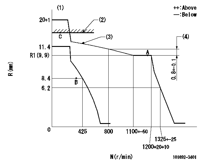
N:Pump speed
R:Rack position (mm)
(1)Target notch: K
(2)RACK CAP: R1
(3)The torque control spring must does not have a set force.
(4)Rack difference between N = N1 and N = N2
----------
K=16 R1=(17.5)mm N1=1200r/min N2=800r/min
----------
----------
K=16 R1=(17.5)mm N1=1200r/min N2=800r/min
----------
Speed control lever angle
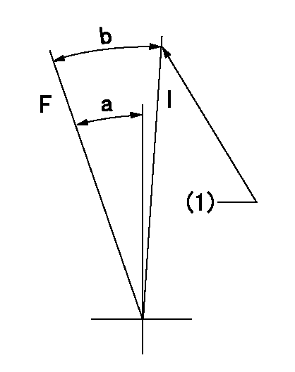
F:Full speed
I:Idle
(1)Stopper bolt setting
----------
----------
a=(21deg)+-5deg b=(25deg)+-5deg
----------
----------
a=(21deg)+-5deg b=(25deg)+-5deg
Stop lever angle
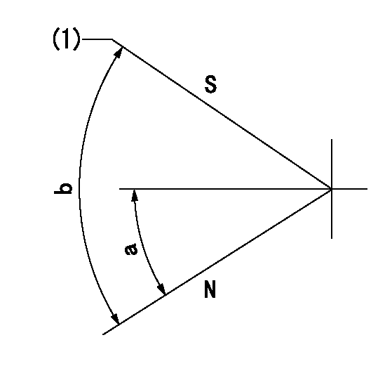
N:Pump normal
S:Stop the pump.
(1)At shipping
----------
----------
a=26.5deg+-5deg b=53deg+-5deg
----------
----------
a=26.5deg+-5deg b=53deg+-5deg
Timing setting

(1)Pump vertical direction
(2)Position of key groove at No 1 cylinder's beginning of injection
(3)Stamp aligning marks on the pump housing flange.
(4)-
(5)-
----------
----------
a=59deg36min+-3deg b=0deg24min+-30min
----------
----------
a=59deg36min+-3deg b=0deg24min+-30min
Information:
3176 ATAAC Truck Engine Model Views
Oil Filter (1), Coolant Conditioner Element (2), Thermostat Housing (3), Oil Filter (4) and Turbocharger (5).
Fuel Filter and Priming Pump (6), Electronic Governor and Personality Module (7), Crankcase Breather (8), Grounding Stud (9).Engine Information
The Caterpillar 3176 ATAAC Diesel Truck engine is an 629 cu.in. (10.3 L) displacement, 4.9 in. (125 mm) bore, 5.5 in. (140 mm) stroke, four stroke cycle, 6 cylinder engine. The firing order is 1-5-3-6-2-4 and the direction of rotation is counterclockwise, as viewed from the flywheel. The 3176 is an electronically controlled, mechanically actuated unit injector diesel engine. Timing advance is achieved by precise control of injector firing. Engine speed is controlled by adjusting the firing duration. A speed timing sensor provides information to the fuel cooled ECM (Electronic Control Module) for detection of cylinder position and engine speed.The 3176 electronic engine control system was designed to provide electronic governing, automatic air-fuel ratio control, torque rise shaping, injection timing control and system diagnostics.Additional benefits such as improved cold starting capability, tamper resistance, diagnostics, cruise control, vehicle speed limiting, progressive shift engine speed control, PTO governor and American Trucking Association (ATA) data link and an Engine Monitoring Package (if equipped) provide for additional engine fuel economy, driver comfort and serviceability.The fuel system is a mechanically actuated, electronically controlled unit injector combining the pumping, electronic fuel metering and injecting elements in a single unit to produce higher injection pressures (22,000 psi [151 600 kPa]). High injection pressures help to reduce fuel consumption and particulate emissions.The use of this type of unit injector provides total electronic control of injection timing. The injection timing is varied as a function of engine operating conditions. This optimizes the engine's performance for starting, emissions, noise, fuel consumption and driveability.The 3176 has built-in diagnostics to assure that all components are functioning and operating properly. In the event of a system component deviation from programmed limits, the operator will be alerted to the condition by a dashboard mounted CHECK ENGINE/DIAGNOSTIC lamp.A Caterpillar service tool may be used to read the numerical code of the faulty component. Intermittent faults are logged and stored in the system memory. Refer to Engine Diagnostics section of this publication for alternative methods.The cooling system consists of a gear driven centrifugal pump, with one thermostat which regulates the engine coolant water temperature, a plate type oil cooler and a radiator incorporating a shunt system.The 3176 does not have a cylinder block water cooling system. Instead, the cast water manifold in the spacer deck distributes 65% of the coolant volume to each of the cylinder liners and the remaining 35% flows directly to the cylinder head.The engine lubricating oil, which is both cooled and filtered, is supplied by a gear-type pump. Bypass valves provide unrestricted flow of lubrication oil to the engine parts when oil viscosity is high, or if either the oil cooler or the oil filter elements (paper cartridge) should become plugged.Engine efficiency, efficiency of emission controls and engine performance depend on adherence