Information injection-pump assembly
ZEXEL
101692-3391
1016923391
Rating:
Cross reference number
ZEXEL
101692-3391
1016923391
Zexel num
Bosch num
Firm num
Name
101692-3391
KOMATSU
INJECTION-PUMP ASSEMBLY
S6D95L *
S6D95L *
Calibration Data:
Adjustment conditions
Test oil
1404 Test oil ISO4113 or {SAEJ967d}
1404 Test oil ISO4113 or {SAEJ967d}
Test oil temperature
degC
40
40
45
Nozzle and nozzle holder
105780-8140
Bosch type code
EF8511/9A
Nozzle
105780-0000
Bosch type code
DN12SD12T
Nozzle holder
105780-2080
Bosch type code
EF8511/9
Opening pressure
MPa
17.2
Opening pressure
kgf/cm2
175
Injection pipe
Outer diameter - inner diameter - length (mm) mm 6-2-600
Outer diameter - inner diameter - length (mm) mm 6-2-600
Tester oil delivery pressure
kPa
157
157
157
Tester oil delivery pressure
kgf/cm2
1.6
1.6
1.6
Direction of rotation (viewed from drive side)
Right R
Right R
Injection timing adjustment
Direction of rotation (viewed from drive side)
Right R
Right R
Injection order
1-5-3-6-
2-4
Pre-stroke
mm
3.6
3.55
3.65
Beginning of injection position
Drive side NO.1
Drive side NO.1
Difference between angles 1
Cal 1-5 deg. 60 59.5 60.5
Cal 1-5 deg. 60 59.5 60.5
Difference between angles 2
Cal 1-3 deg. 120 119.5 120.5
Cal 1-3 deg. 120 119.5 120.5
Difference between angles 3
Cal 1-6 deg. 180 179.5 180.5
Cal 1-6 deg. 180 179.5 180.5
Difference between angles 4
Cyl.1-2 deg. 240 239.5 240.5
Cyl.1-2 deg. 240 239.5 240.5
Difference between angles 5
Cal 1-4 deg. 300 299.5 300.5
Cal 1-4 deg. 300 299.5 300.5
Injection quantity adjustment
Adjusting point
A
Rack position
11.7
Pump speed
r/min
1450
1450
1450
Average injection quantity
mm3/st.
67.3
66.3
68.3
Max. variation between cylinders
%
0
-2.5
2.5
Basic
*
Fixing the lever
*
Injection quantity adjustment_02
Adjusting point
-
Rack position
9.5+-0.5
Pump speed
r/min
450
450
450
Average injection quantity
mm3/st.
12.5
11.5
13.5
Max. variation between cylinders
%
0
-15
15
Fixing the rack
*
Remarks
Adjust only variation between cylinders; adjust governor according to governor specifications.
Adjust only variation between cylinders; adjust governor according to governor specifications.
Test data Ex:
Governor adjustment
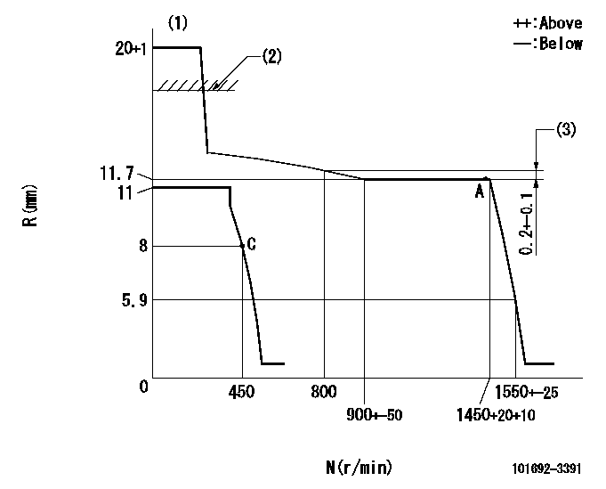
N:Pump speed
R:Rack position (mm)
(1)Target notch: K
(2)RACK CAP: R1
(3)Rack difference between N = N1 and N = N2
----------
K=9 R1=(17.5)mm N1=1450r/min N2=800r/min
----------
----------
K=9 R1=(17.5)mm N1=1450r/min N2=800r/min
----------
Speed control lever angle
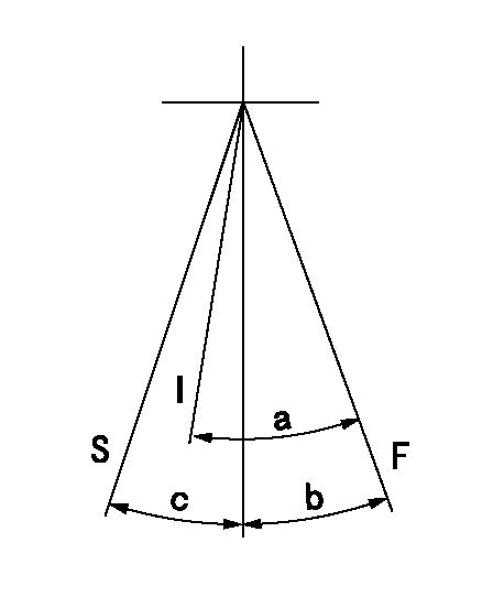
F:Full speed
I:Idle
S:Stop
----------
----------
a=31deg+-5deg b=12deg+-5deg c=32deg+-3deg
----------
----------
a=31deg+-5deg b=12deg+-5deg c=32deg+-3deg
Timing setting

(1)Pump vertical direction
(2)Position of key groove at No 1 cylinder's beginning of injection
(3)Stamp aligning marks on the pump housing flange.
(4)-
(5)-
----------
----------
a=59deg36min+-3deg b=0deg24min+-30min
----------
----------
a=59deg36min+-3deg b=0deg24min+-30min
Information:
Literature Information
This manual contains safety, operation instructions, lubrication and maintenance information. Read-study-and keep it with the truck literature and engine information.Some photographs or illustrations in this publication show details or attachments that may be different from your engine. Guards and covers may have been removed for illustrative purposes. Continuing improvement and advancement of product design may have caused changes to your engine which are not included in this publication.Whenever a question arises regarding your engine, or this publication, please consult your Caterpillar dealer for the latest available information.Safety
The safety section lists basic safety precautions. In addition, this section identifies the text and locations of warning labels used on the engine. Read and understand the basic precautions listed in the safety section before operating or performing lubrication, maintenance and repair on this product.Operation
Operating techniques outlined in this publication are basic. This manual will assist you with developing the skills and techniques required to operate your engine more efficiently and economically.The operation section is a reference for operators. Photographs and illustrations guide the operator through correct procedures of inspecting, starting, operating and stopping the engine. This section also includes a discussion of gauges, protection devices, lifting and storage information.Maintenance
The maintenance section is a guide to engine care. The illustrated, step-by-step instructions are grouped by Preventive Maintenance servicing intervals. Items in the Maintenance Schedule are referenced to detailed instructions that follow.Recommended service should always be performed at the interval that occurs first (i.e. fuel consumption figure, distance [odometer] traveled or service hours). Under very severe, dusty or freezing cold operating conditions, more frequent maintenance than is specified in the Maintenance Schedule may be necessary. Refer to the Severe Service Application topics in this publication for the information.Maintenance Intervals
Perform maintenance on items at multiples of the original requirement. The maintenance interval for each item listed in the Maintenance Schedule is primarily based on the item and its relationship to either engine speed or load.We recommend that a maintenance record be maintained as part of the engine's permanent record. See the Maintenance Records section of this publication for information regarding documents that are generally accepted as proof of maintenance or repair. Your authorized Caterpillar dealer can assist you in tailoring your Maintenance Schedule to meet the needs of your operating environment.Overhaul
Major engine repair such as overhaul is not covered in this manual. Major repairs are best left to the trained personnel of an authorized Caterpillar dealer. Your Caterpillar dealer offers a variety of options regarding overhaul programs. Contact your dealer for information regarding these options. If you experience a major engine failure which necessitates removal of the engine from the chassis, there are numerous overhaul options available from your Caterpillar dealer.Engine Description
The engines described in this publication are the 3176 ATAAC Diesel Truck engines equipped with electronic fuel system. They are designed primarily for on-highway medium to heavy duty applications.Engine Storage
For general information, refer to the Engine Lifting & Storage topic. For complete engine storage information refer to SEHS9031, Storage Procedure for Caterpillar Products.
Have questions with 101692-3391?
Group cross 101692-3391 ZEXEL
Komatsu
Komatsu
101692-3391
INJECTION-PUMP ASSEMBLY
S6D95L
S6D95L