Information injection-pump assembly
ZEXEL
101692-2720
1016922720
HINO
220201212A
220201212a
Rating:
Service parts 101692-2720 INJECTION-PUMP ASSEMBLY:
1.
_
5.
AUTOM. ADVANCE MECHANIS
7.
COUPLING PLATE
8.
_
9.
_
10.
NOZZLE AND HOLDER ASSY
11.
Nozzle and Holder
12.
Open Pre:MPa(Kqf/cm2)
13.
NOZZLE-HOLDER
15.
NOZZLE SET
Cross reference number
ZEXEL
101692-2720
1016922720
HINO
220201212A
220201212a
Zexel num
Bosch num
Firm num
Name
Calibration Data:
Adjustment conditions
Test oil
1404 Test oil ISO4113 or {SAEJ967d}
1404 Test oil ISO4113 or {SAEJ967d}
Test oil temperature
degC
40
40
45
Nozzle and nozzle holder
105780-8140
Bosch type code
EF8511/9A
Nozzle
105780-0000
Bosch type code
DN12SD12T
Nozzle holder
105780-2080
Bosch type code
EF8511/9
Opening pressure
MPa
17.2
Opening pressure
kgf/cm2
175
Injection pipe
Outer diameter - inner diameter - length (mm) mm 6-2-600
Outer diameter - inner diameter - length (mm) mm 6-2-600
Tester oil delivery pressure
kPa
157
157
157
Tester oil delivery pressure
kgf/cm2
1.6
1.6
1.6
Direction of rotation (viewed from drive side)
Right R
Right R
Injection timing adjustment
Direction of rotation (viewed from drive side)
Right R
Right R
Injection order
1-4-2-6-
3-5
Pre-stroke
mm
2.1
2.05
2.15
Rack position
After adjusting injection quantity. R=A
After adjusting injection quantity. R=A
Beginning of injection position
Drive side NO.1
Drive side NO.1
Difference between angles 1
Cal 1-4 deg. 60 59.5 60.5
Cal 1-4 deg. 60 59.5 60.5
Difference between angles 2
Cyl.1-2 deg. 120 119.5 120.5
Cyl.1-2 deg. 120 119.5 120.5
Difference between angles 3
Cal 1-6 deg. 180 179.5 180.5
Cal 1-6 deg. 180 179.5 180.5
Difference between angles 4
Cal 1-3 deg. 240 239.5 240.5
Cal 1-3 deg. 240 239.5 240.5
Difference between angles 5
Cal 1-5 deg. 300 299.5 300.5
Cal 1-5 deg. 300 299.5 300.5
Injection quantity adjustment
Adjusting point
A
Rack position
13.2
Pump speed
r/min
800
800
800
Average injection quantity
mm3/st.
120.1
117.6
122.6
Max. variation between cylinders
%
0
-2
2
Basic
*
Fixing the lever
*
Injection quantity adjustment_02
Adjusting point
D
Rack position
6.1+-0.5
Pump speed
r/min
250
250
250
Average injection quantity
mm3/st.
13.2
10.7
15.7
Max. variation between cylinders
%
0
-13
13
Fixing the rack
*
Test data Ex:
Governor adjustment
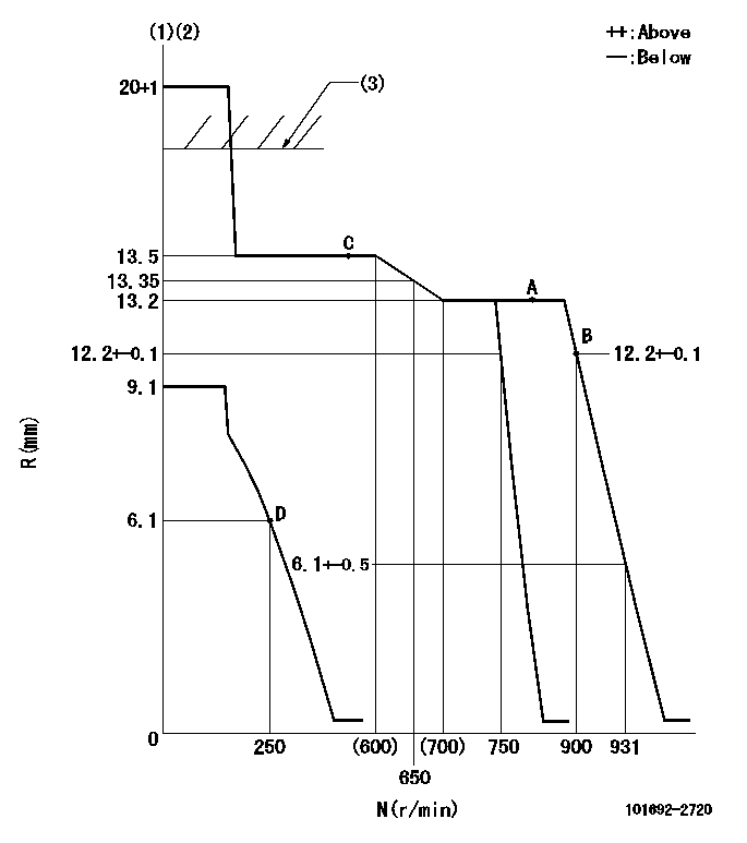
N:Pump speed
R:Rack position (mm)
(1)Target notch: K
(2)Tolerance for racks not indicated: +-0.05mm.
(3)RACK CAP: R1
----------
K=17 R1=(17.5)mm
----------
----------
K=17 R1=(17.5)mm
----------
Speed control lever angle
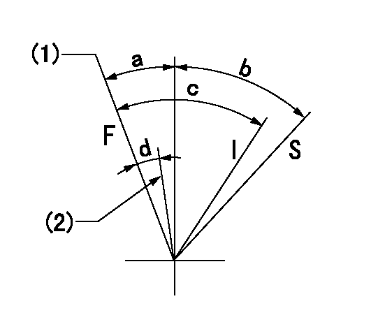
F:Full speed
I:Idle
S:Stop
(1)Speed set at aa (setting at shipping)
(2)Set the pump speed at bb.
----------
aa=900r/min bb=750r/min
----------
a=15.5deg+-5deg b=32deg+-3deg c=40deg+-5deg d=10deg+-5deg
----------
aa=900r/min bb=750r/min
----------
a=15.5deg+-5deg b=32deg+-3deg c=40deg+-5deg d=10deg+-5deg
Stop lever angle
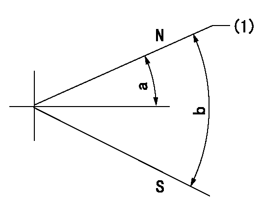
N:Pump normal
S:Stop the pump.
(1)Normal
----------
----------
a=19deg+-5deg b=53deg+-5deg
----------
----------
a=19deg+-5deg b=53deg+-5deg
Information:
Engine Lifting
When it is necessary to remove a component on an angle, remember that the capacity of an eyebolt is less as the angle between the supporting members and the object becomes less than 90 degrees. Eye Bolts and brackets should never be bent, and should only be loaded under tension.
Use a hoist to remove heavy components. Use an adjustable lifting beam to lift the engine. All supporting members (chains and cables) should be parallel to each other, and perpendicular as possible to the top of the object being lifted.Some removals require the use of lifting fixtures, to obtain proper balance and provide safe handling.To remove the engine ONLY, use the lifting eyes equipped with the engine.The lifting eyes are designed for the engine arrangement as sold. Modifying the lifting eyes and/or engine arrangement weight renders the lifting eyes and devices obsolete.If you modify the lifting eyes and/or engine arrangement weight, you are responsible for providing adequate lifting devices. Contact your Caterpillar dealer for information regarding fixtures for proper engine package lifting.Engine Lifting With Generator
Do not use the engine lifting eyes to remove the engine and generator together.Lifting the engine and generator together requires special equipment and procedures. Contact your Caterpillar dealer for information regarding fixtures for proper lifting of your engine package.Engine Lifting With Fuel Tank
Lifting the engine along with a mounted fuel tank requires special equipment and procedures. Do not lift the unit with fuel in the tank. Contact your Caterpillar dealer for information regarding proper engine and fuel tank lifting.Engine Storage
The following Engine Storage procedures and recommendations minimize the possibility of damage to engines stored for one year or less.When an engine is not started for several weeks, the lubricating oil drains from the cylinder walls and piston rings. Rust can then form on the cylinder liner surface, increasing engine wear and decreasing engine life.Special precautions should be used with engines remaining out of service for extended periods.After one year, a complete protection procedure must be followed if the engine is kept in storage longer. To prevent excessive engine wear: * Be sure all lubrication recommendations mentioned in the Maintenance Schedule intervals chart are completed.* If freezing temperatures are expected, check the cooling system for adequate protection against freezing. A 50/50 solution of Caterpillar (permanent-type) Antifreeze and approved water will give protection to -29°C (-20°F).If it will be impossible to start the engine periodically, consult your Caterpillar dealer for instructions to prepare your engine for longer storage periods.Refer to Storage Procedures For Caterpillar Products, SEHS9031, for more detailed information on engine storage.Generator Storage Procedure
When a generator is stored, moisture may condense in the windings. Use a dry storage space and space heaters to minimize condensation. Refer to: Service Manual for SR4 Generators, SENR3985, or Special Instruction, SEHS9124, Cleaning and Drying of Caterpillar Electric Set Generators, or contact your Caterpillar dealer.After Storage
Test the main stator windings with a megohmmeter: * Before the initial startup of the generator set.* Every 3 months* if the generator is operating