Information injection-pump assembly
ZEXEL
101692-2520
1016922520
HINO
220201220A
220201220a
Rating:
Service parts 101692-2520 INJECTION-PUMP ASSEMBLY:
1.
_
5.
AUTOM. ADVANCE MECHANIS
7.
COUPLING PLATE
8.
_
9.
_
10.
NOZZLE AND HOLDER ASSY
11.
Nozzle and Holder
12.
Open Pre:MPa(Kqf/cm2)
13.
NOZZLE-HOLDER
15.
NOZZLE SET
Cross reference number
ZEXEL
101692-2520
1016922520
HINO
220201220A
220201220a
Zexel num
Bosch num
Firm num
Name
Calibration Data:
Adjustment conditions
Test oil
1404 Test oil ISO4113 or {SAEJ967d}
1404 Test oil ISO4113 or {SAEJ967d}
Test oil temperature
degC
40
40
45
Nozzle
105780-0020
Bosch type code
DN4SD24T
Nozzle holder
105031-2010
Bosch type code
KB56SD273
Opening pressure
MPa
16
Opening pressure
kgf/cm2
120
Injection pipe
Outer diameter - inner diameter - length (mm) mm 6-2-600
Outer diameter - inner diameter - length (mm) mm 6-2-600
Overflow valve
132424-0620
Overflow valve opening pressure
kPa
157
123
191
Overflow valve opening pressure
kgf/cm2
1.6
1.25
1.95
Tester oil delivery pressure
kPa
157
157
157
Tester oil delivery pressure
kgf/cm2
1.6
1.6
1.6
Direction of rotation (viewed from drive side)
Right R
Right R
Injection timing adjustment
Direction of rotation (viewed from drive side)
Right R
Right R
Injection order
1-4-2-6-
3-5
Pre-stroke
mm
2.1
2.05
2.15
Beginning of injection position
Drive side NO.1
Drive side NO.1
Difference between angles 1
Cal 1-4 deg. 60 59.5 60.5
Cal 1-4 deg. 60 59.5 60.5
Difference between angles 2
Cyl.1-2 deg. 120 119.5 120.5
Cyl.1-2 deg. 120 119.5 120.5
Difference between angles 3
Cal 1-6 deg. 180 179.5 180.5
Cal 1-6 deg. 180 179.5 180.5
Difference between angles 4
Cal 1-3 deg. 240 239.5 240.5
Cal 1-3 deg. 240 239.5 240.5
Difference between angles 5
Cal 1-5 deg. 300 299.5 300.5
Cal 1-5 deg. 300 299.5 300.5
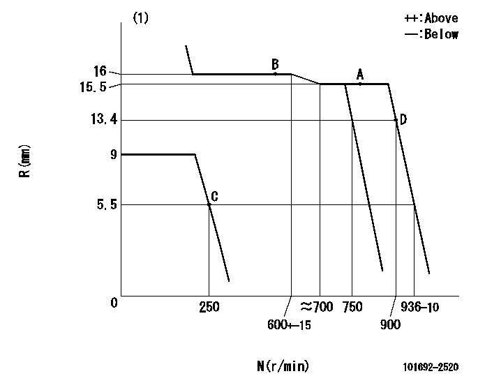
Injection quantity adjustment
Adjusting point
A
Rack position
15.5
Pump speed
r/min
800
800
800
Average injection quantity
mm3/st.
146
143
149
Max. variation between cylinders
%
0
-2
2
Basic
*
Fixing the lever
*
Injection quantity adjustment_02
Adjusting point
B
Rack position
16
Pump speed
r/min
500
500
500
Average injection quantity
mm3/st.
143
138.5
147.5
Max. variation between cylinders
%
0
-3
3
Fixing the rack
*
Injection quantity adjustment_03
Adjusting point
C
Rack position
5.5+-0.5
Pump speed
r/min
250
250
250
Average injection quantity
mm3/st.
20
17.5
22.5
Max. variation between cylinders
%
0
-13
13
Fixing the rack
*
Injection quantity adjustment_04
Adjusting point
D
Rack position
13.4
Pump speed
r/min
900
900
900
Average injection quantity
mm3/st.
134
128.8
139.2
Max. variation between cylinders
%
0
-4
4
Fixing the rack
*
Test data Ex:
Governor adjustment
N:Pump speed
R:Rack position (mm)
(1)Target notch: K
----------
K=10
----------
----------
K=10
----------
Speed control lever angle
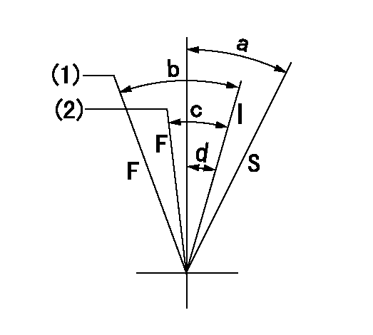
F:Full speed
I:Idle
S:Stop
(1)Set the pump speed at aa
(2)Set the pump speed at bb.
----------
aa=900r/min bb=750r/min
----------
a=32deg+-3deg b=32.5deg+-5deg c=25.5deg+-5deg d=25deg
----------
aa=900r/min bb=750r/min
----------
a=32deg+-3deg b=32.5deg+-5deg c=25.5deg+-5deg d=25deg
Information:
Air-to-air aftercooling systems are simple, reliable and easy to maintain and provide for one or more benefits.* Improved fuel consumption* Lower emissions* Increased powerOperation of ATAAC
Heated compressed air from the engine turbocharger is conveyed to an air-to-air aftercooler that is positioned in front of the engine radiator. The combined effect of the engine fan and ram air moves cooled air through the system to reduce the turbocharged air temperature before it enters the engine intake manifold.Lower intake air temperature allows more air to enter the cylinder, resulting in more complete fuel combustion and reduced exhaust emissions.Air-to-air aftercoolers can achieve charge air temperatures lower than water-to-air systems for additional efficiency.
To maintain an adequate water pump cavitation temperature for efficient water pump performance in an Air-to-Air aftercooled engine, Caterpillar recommends that the coolant mix contain a minimum of 30% Caterpillar Antifreeze, GM-6038M or equivalent. Only use a greater concentration (above 30%) of antifreeze as needed for anticipated outside temperatures.Ethylene glycol raises the boiling point of water.Do not exceed a coolant mixture of 60% ethylene glycol to water since a concentration above 60% ethylene glycol will reduce the engine's freeze protection and increase the possibility of deposit formation in the cooling system.Downtherm 209 Full-Fill coolant cannot be substituted for ethylene glycol, due to its inability to raise the water pump cavitation temperature. Downtherm 209 Full-Fill coolant lowers the boiling point of water.
Air Intake System
Never run the engine without an air cleaner installed or with a damaged air cleaner. Dirt will enter the engine and cause premature wear and damage to engine components.Service the air cleaner at regular intervals as determined by the operating environmental dust conditions. Check the air cleaner service indicator (if equipped) daily.As the air cleaner element becomes plugged, the difference of air pressure between the inlet side (dirty side) and the engine side (clean side) will increase. Service the air cleaners regularly or when the air cleaner service indicator diaphragm enters the red zone or the red piston locks in the visible position.Inspect the air intake hoses, elbows and gaskets for cracks or damage, replace as needed. Check for loose clamps, tighten as needed.Check the precleaner (if equipped) daily for accumulation of dust and debris.The Caterpillar air cleaner element may be cleaned up to six times, but must be replaced annually. The element when cleaned, should be thoroughly checked for rips and tears in the filter material and for gasket damage.Winter Fronts
Caterpillar discourages the use of winter fronts or other air flow restriction devices mounted in front of radiators with air-to-air aftercooled engines. Air flow restriction can cause higher exhaust temperatures, power loss, excessive fan usage, a reduction in fuel economy and possible engine damage.If a winter front must be used, then it should have a permanent circular or diamond-shaped opening directly in line with the fan hub and must have a minimum opening dimension of at least 120 sq. in. (770 sq. cm).A centered opening, versus a side or edge winter front opening is specified to provide