Information injection-pump assembly
ZEXEL
101691-9913
1016919913

Rating:
Service parts 101691-9913 INJECTION-PUMP ASSEMBLY:
1.
_
7.
COUPLING PLATE
8.
_
9.
_
11.
Nozzle and Holder
16600-95015
12.
Open Pre:MPa(Kqf/cm2)
19.6{200}
15.
NOZZLE SET
Cross reference number
ZEXEL
101691-9913
1016919913
Zexel num
Bosch num
Firm num
Name
101691-9913
INJECTION-PUMP ASSEMBLY
Calibration Data:
Adjustment conditions
Test oil
1404 Test oil ISO4113 or {SAEJ967d}
1404 Test oil ISO4113 or {SAEJ967d}
Test oil temperature
degC
40
40
45
Nozzle and nozzle holder
105780-8140
Bosch type code
EF8511/9A
Nozzle
105780-0000
Bosch type code
DN12SD12T
Nozzle holder
105780-2080
Bosch type code
EF8511/9
Opening pressure
MPa
17.2
Opening pressure
kgf/cm2
175
Injection pipe
Outer diameter - inner diameter - length (mm) mm 6-2-600
Outer diameter - inner diameter - length (mm) mm 6-2-600
Overflow valve opening pressure
kPa
157
123
191
Overflow valve opening pressure
kgf/cm2
1.6
1.25
1.95
Tester oil delivery pressure
kPa
157
157
157
Tester oil delivery pressure
kgf/cm2
1.6
1.6
1.6
Direction of rotation (viewed from drive side)
Right R
Right R
Injection timing adjustment
Direction of rotation (viewed from drive side)
Right R
Right R
Injection order
1-4-2-6-
3-5
Pre-stroke
mm
3.7
3.65
3.75
Beginning of injection position
Drive side NO.1
Drive side NO.1
Difference between angles 1
Cal 1-4 deg. 60 59.5 60.5
Cal 1-4 deg. 60 59.5 60.5
Difference between angles 2
Cyl.1-2 deg. 120 119.5 120.5
Cyl.1-2 deg. 120 119.5 120.5
Difference between angles 3
Cal 1-6 deg. 180 179.5 180.5
Cal 1-6 deg. 180 179.5 180.5
Difference between angles 4
Cal 1-3 deg. 240 239.5 240.5
Cal 1-3 deg. 240 239.5 240.5
Difference between angles 5
Cal 1-5 deg. 300 299.5 300.5
Cal 1-5 deg. 300 299.5 300.5
Injection quantity adjustment
Adjusting point
-
Rack position
13.7
Pump speed
r/min
1400
1400
1400
Average injection quantity
mm3/st.
109
107.4
110.6
Max. variation between cylinders
%
0
-3.5
3.5
Basic
*
Fixing the rack
*
Standard for adjustment of the maximum variation between cylinders
*
Injection quantity adjustment_02
Adjusting point
-
Rack position
9.8+-0.5
Pump speed
r/min
275
275
275
Average injection quantity
mm3/st.
9
7.2
10.8
Max. variation between cylinders
%
0
-10
10
Fixing the rack
*
Standard for adjustment of the maximum variation between cylinders
*
Remarks
Adjust only variation between cylinders; adjust governor according to governor specifications.
Adjust only variation between cylinders; adjust governor according to governor specifications.
Injection quantity adjustment_03
Adjusting point
A
Rack position
R1(13.7)
Pump speed
r/min
1400
1400
1400
Average injection quantity
mm3/st.
109
108
110
Basic
*
Fixing the lever
*
Boost pressure
kPa
30.7
30.7
Boost pressure
mmHg
230
230
Injection quantity adjustment_04
Adjusting point
B
Rack position
R1-0.1
Pump speed
r/min
900
900
900
Average injection quantity
mm3/st.
101.4
99.4
103.4
Fixing the lever
*
Boost pressure
kPa
30.7
30.7
Boost pressure
mmHg
230
230
Injection quantity adjustment_05
Adjusting point
C
Rack position
R2(12.6)
Pump speed
r/min
400
400
400
Average injection quantity
mm3/st.
61.6
59.6
63.6
Fixing the lever
*
Boost pressure
kPa
0
0
0
Boost pressure
mmHg
0
0
0
Injection quantity adjustment_06
Adjusting point
I
Rack position
-
Pump speed
r/min
150
150
150
Average injection quantity
mm3/st.
85
85
105
Fixing the lever
*
Rack limit
*
Boost compensator adjustment
Pump speed
r/min
600
600
600
Rack position
R3(12)
Boost pressure
kPa
4
2.7
5.3
Boost pressure
mmHg
30
20
40
Boost compensator adjustment_02
Pump speed
r/min
600
600
600
Rack position
R3+0.4
Boost pressure
kPa
9.3
8
10.6
Boost pressure
mmHg
70
60
80
Boost compensator adjustment_03
Pump speed
r/min
600
600
600
Rack position
R1-0.6
Boost pressure
kPa
17.3
17.3
17.3
Boost pressure
mmHg
130
130
130
Timer adjustment
Pump speed
r/min
920--
Advance angle
deg.
0
0
0
Remarks
Start
Start
Timer adjustment_02
Pump speed
r/min
870
Advance angle
deg.
0.5
Timer adjustment_03
Pump speed
r/min
1400
Advance angle
deg.
2
1.5
2.5
Remarks
Finish
Finish
Test data Ex:
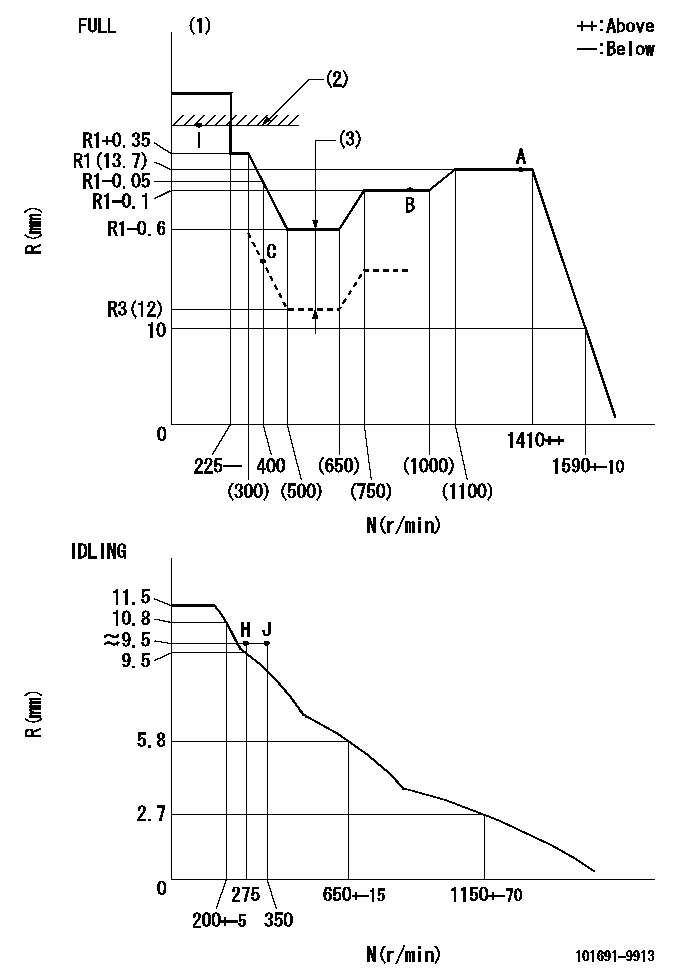
Governor adjustment

N:Pump speed
R:Rack position (mm)
(1)Torque cam stamping: T1
(2)RACK LIMIT
(3)Boost compensator stroke: BCL
----------
T1=B36 BCL=(1.1)+-0.1mm
----------
----------
T1=B36 BCL=(1.1)+-0.1mm
----------
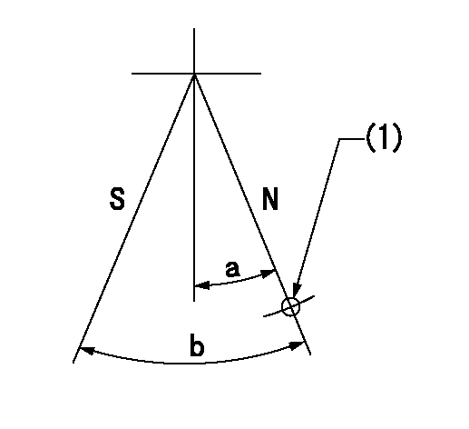
Speed control lever angle

F:Full speed
I:Idle
(1)Use the hole at R = aa
(2)Stopper bolt set position 'H'
----------
aa=100mm
----------
a=26.5deg+-5deg b=42deg+-3deg
----------
aa=100mm
----------
a=26.5deg+-5deg b=42deg+-3deg
Stop lever angle

N:Pump normal
S:Stop the pump.
(1)Use the hole at R = aa
----------
aa=36mm
----------
a=20deg+-5deg b=40deg+-5deg
----------
aa=36mm
----------
a=20deg+-5deg b=40deg+-5deg
Timing setting

(1)Pump vertical direction
(2)Coupling's key groove position at No 1 cylinder's beginning of injection
(3)-
(4)-
----------
----------
a=(40deg)
----------
----------
a=(40deg)
Information:
The standard engine includes the features of programmable low idle and top engine limiting (TEL). Cruise control, PTO governing, vehicle speed limiting, low and high gears engine rpm limiting (progressive shift control), retarder coast/latch and idle shutdown timer are also available depending on OEM truck configurations.If equipped, the 3176 engine system is capable of being programmed for several customer specified parameters. These parameters are generally programmed so the vehicle will achieve optimum fuel efficiency and operator convenience.Low idle and top engine rpm limits are customer programmable to promote maximum fuel efficiency. The 3176 system allows the owner to select power ratings within a "family" to more efficiently match the vehicle to the application.The customer specified parameters and a brief explanation of each are as follows:1. Engine Power Rating - The 3176 engine is designed to provide full rated power over a large range of engine speeds. For example, the Caterpillar 3176 ATAAC Truck Engine ratings for the 19911 are:* 250 hp (187 kW) @ 1800 rpm* 275 hp (205 kW) @ 1800 rpm* 300 hp (224 kW) @ 1800 rpm* 325 hp (242 kW) @ 1800 rpm* 250 hp (187 kW) @ 2100 rpm* 275 hp (205 kW) @ 2100 rpm* 300 hp (224 kW) @ 2100 rpm* 325 hp (242 kW) @ 2100 rpm1These ratings are available factory-set from Caterpillar, they are EPA, CARB (50-state) and Canada emission certified. Other ratings may be programmed either at the OEM or in the field.2. Vehicle Identification Number - The owner's description, or unit number of the vehicle. 3. PTO Vehicle Speed Limit (PTO VSL) - Maximum vehicle speed at which the PTO Governor will function.4. PTO Engine RPM Limit (PTO RPM) - Maximum engine rpm attainable using the CRUISE CONTROL switches while the vehicle is operated below the PTO VSL (generally used for maximum rpm limit for overnight idling). 5. Low Gears #1 RPM Limit (LoGr #1) - The rpm at which the engine is limited in the lowest gears.6. Low Gears #2 RPM Limit (LoGr #2) - The rpm at which the engine is limited in a secondary gear range.7. Low Gears Turn Off Speed (LoGr Off Limits) - The vehicle speeds at which LoGr #1 and LoGr #2 turn off. 8. High Gears rpm Limit (HiGr rpm) - The rpm at which the engine is limited in the higher gears (generally used to encourage shifting into higher gears).9. High Gear Turn On Speed (HiGr On) - The vehicle speed at which High Gear rpm is in effect.10. Top Engine Limit (TEL) - Maximum allowable engine rpm generally set at rated rpm [rpm at which maximum power is developed] plus (+) 20 rpm. 11. Engine rpm at Vehicle Speed Limit (Eng rpm at VSL) - The engine rpm achieved in high (top) gear at VSL. Interruption of the vehicle speed input to the 3176 System will limit engine rpm to this value at all vehicle speeds.12. Vehicle Speed Limit (VSL) - Maximum vehicle speed.13. Low Engine Idle rpm
Have questions with 101691-9913?
Group cross 101691-9913 ZEXEL
Nissan-Diesel
Nissan-Diesel
101691-9913
INJECTION-PUMP ASSEMBLY