Information injection-pump assembly
ZEXEL
101691-9890
1016919890
NISSAN-DIESEL
16801Z5502
16801z5502

Rating:
Cross reference number
ZEXEL
101691-9890
1016919890
NISSAN-DIESEL
16801Z5502
16801z5502
Zexel num
Bosch num
Firm num
Name
Calibration Data:
Adjustment conditions
Test oil
1404 Test oil ISO4113 or {SAEJ967d}
1404 Test oil ISO4113 or {SAEJ967d}
Test oil temperature
degC
40
40
45
Nozzle and nozzle holder
105780-8140
Bosch type code
EF8511/9A
Nozzle
105780-0000
Bosch type code
DN12SD12T
Nozzle holder
105780-2080
Bosch type code
EF8511/9
Opening pressure
MPa
17.2
Opening pressure
kgf/cm2
175
Injection pipe
Outer diameter - inner diameter - length (mm) mm 6-2-600
Outer diameter - inner diameter - length (mm) mm 6-2-600
Overflow valve
132424-0620
Overflow valve opening pressure
kPa
157
123
191
Overflow valve opening pressure
kgf/cm2
1.6
1.25
1.95
Tester oil delivery pressure
kPa
157
157
157
Tester oil delivery pressure
kgf/cm2
1.6
1.6
1.6
RED3 control unit part number
407910-2
470
RED3 rack sensor specifications
mm
15
Direction of rotation (viewed from drive side)
Right R
Right R
Injection timing adjustment
Direction of rotation (viewed from drive side)
Right R
Right R
Injection order
1-4-2-6-
3-5
Pre-stroke
mm
3.4
3.35
3.45
Beginning of injection position
Drive side NO.1
Drive side NO.1
Difference between angles 1
Cal 1-4 deg. 60 59.5 60.5
Cal 1-4 deg. 60 59.5 60.5
Difference between angles 2
Cyl.1-2 deg. 120 119.5 120.5
Cyl.1-2 deg. 120 119.5 120.5
Difference between angles 3
Cal 1-6 deg. 180 179.5 180.5
Cal 1-6 deg. 180 179.5 180.5
Difference between angles 4
Cal 1-3 deg. 240 239.5 240.5
Cal 1-3 deg. 240 239.5 240.5
Difference between angles 5
Cal 1-5 deg. 300 299.5 300.5
Cal 1-5 deg. 300 299.5 300.5
Injection quantity adjustment
Rack position
(12.7)
Vist
V
1.45
1.45
1.45
Pump speed
r/min
550
550
550
Average injection quantity
mm3/st.
87.1
86.1
88.1
Max. variation between cylinders
%
0
-3.5
3.5
Basic
*
Injection quantity adjustment_02
Rack position
(8.7)
Vist
V
2.25
2.15
2.35
Pump speed
r/min
275
275
275
Average injection quantity
mm3/st.
9.5
7.7
11.3
Max. variation between cylinders
%
0
-10
10
Test data Ex:
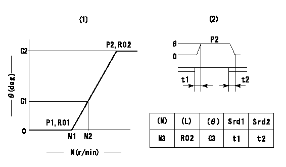
Governor adjustment

(1)Adjusting range
(2)Step response time
(N): Speed of the pump
(L): Load
(theta) Advance angle
(Srd1) Step response time 1
(Srd2) Step response time 2
1. Adjusting conditions for the variable timer
(1)Adjust the clearance between the pickup and the protrusion to L.
----------
L=1.5+-0.2mm N3=800r/min C3=(4deg) t1=2--sec. t2=2--sec.
----------
N1=1200++r/min N2=1400r/min P1=0kPa(0kgf/cm2) P2=392kPa(4kgf/cm2) C1=2.5--deg C2=4+-0.3deg R01=0/4load R02=4/4load
----------
L=1.5+-0.2mm N3=800r/min C3=(4deg) t1=2--sec. t2=2--sec.
----------
N1=1200++r/min N2=1400r/min P1=0kPa(0kgf/cm2) P2=392kPa(4kgf/cm2) C1=2.5--deg C2=4+-0.3deg R01=0/4load R02=4/4load
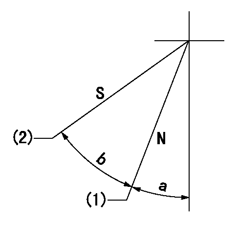
Speed control lever angle

N:Pump normal
S:Stop the pump.
(1)Rack position = aa
(2)Rack position bb
----------
aa=16mm bb=1mm
----------
a=30deg+-5deg b=29deg+-5deg
----------
aa=16mm bb=1mm
----------
a=30deg+-5deg b=29deg+-5deg
0000000901

(1)Pump vertical direction
(2)Position of timer's threaded hole at No 1 cylinder's beginning of injection
(3)-
(4)-
----------
----------
a=(60deg)
----------
----------
a=(60deg)
Stop lever angle

(Rs) rack sensor specifications
(C/U) control unit part number
(V) Rack sensor output voltage
(R) Rack position (mm)
1. Confirming governor output characteristics (rack 15 mm, span 6 mm)
(1)When the output voltages of the rack sensor are V1 and V2, check that the rack positions R1 and R2 in the table above are satisfied.
----------
----------
----------
----------
Information:
Filters and Pump Housing
1. Open the bleed valve on the pump housing. 2. Unscrew the hand priming pump plunger until it can be pulled out by hand. 3. Move the plunger in and out until fuel flows, free of air bubbles, from the bleed valve. 4. Close the bleed valve. 5. Push the plunger in and tighten by hand.6. Start the engine and check for leaks.Injection Pumps and Lines
The injection pumps and high pressure lines must be primed if the engine will not start, or runs rough, after priming the filters and pump housing.Each injection pump has a reverse flow check valve. These cannot be opened with hand priming pump pressure. Use the following procedure to prime the injection pumps and lines.
The fuel injection nozzles can be permanently damaged by twisting if only one wrench is used to loosen or tighten the fuel line nuts. Use one wrench to hold the nozzle and another to loosen the nut.
1. Loosen each of the fuel line nuts at the cylinder head end.2. Crank the engine with the starting motor until fuel flows, free of air bubbles, from each of the injection lines. Stop cranking the engine.3. Tighten each of the fuel line nuts to a torque of 41 + 7 N m (30 + 5 lb. ft.). Use a second wrench on the nozzle to prevent damage to it.4. Start the engine and check for leaks.