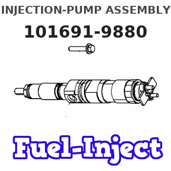
Information injection-pump assembly
ZEXEL
101691-9880
1016919880
NISSAN-DIESEL
16801Z5501
16801z5501
Rating:
Cross reference number
ZEXEL
101691-9880
1016919880
NISSAN-DIESEL
16801Z5501
16801z5501
Zexel num
Bosch num
Firm num
Name
Calibration Data:
Adjustment conditions
Test oil
1404 Test oil ISO4113 or {SAEJ967d}
1404 Test oil ISO4113 or {SAEJ967d}
Test oil temperature
degC
40
40
45
Nozzle and nozzle holder
105780-8140
Bosch type code
EF8511/9A
Nozzle
105780-0000
Bosch type code
DN12SD12T
Nozzle holder
105780-2080
Bosch type code
EF8511/9
Opening pressure
MPa
17.2
Opening pressure
kgf/cm2
175
Injection pipe
Outer diameter - inner diameter - length (mm) mm 6-2-600
Outer diameter - inner diameter - length (mm) mm 6-2-600
Overflow valve
132424-0620
Overflow valve opening pressure
kPa
157
123
191
Overflow valve opening pressure
kgf/cm2
1.6
1.25
1.95
Tester oil delivery pressure
kPa
157
157
157
Tester oil delivery pressure
kgf/cm2
1.6
1.6
1.6
RED3 control unit part number
407910-2
470
RED3 rack sensor specifications
mm
15
Direction of rotation (viewed from drive side)
Right R
Right R
Injection timing adjustment
Direction of rotation (viewed from drive side)
Right R
Right R
Injection order
1-4-2-6-
3-5
Pre-stroke
mm
3.4
3.35
3.45
Beginning of injection position
Drive side NO.1
Drive side NO.1
Difference between angles 1
Cal 1-4 deg. 60 59.5 60.5
Cal 1-4 deg. 60 59.5 60.5
Difference between angles 2
Cyl.1-2 deg. 120 119.5 120.5
Cyl.1-2 deg. 120 119.5 120.5
Difference between angles 3
Cal 1-6 deg. 180 179.5 180.5
Cal 1-6 deg. 180 179.5 180.5
Difference between angles 4
Cal 1-3 deg. 240 239.5 240.5
Cal 1-3 deg. 240 239.5 240.5
Difference between angles 5
Cal 1-5 deg. 300 299.5 300.5
Cal 1-5 deg. 300 299.5 300.5
Injection quantity adjustment
Rack position
(13)
Vist
V
1.4
1.4
1.4
Pump speed
r/min
550
550
550
Average injection quantity
mm3/st.
84.1
83.1
85.1
Max. variation between cylinders
%
0
-3.5
3.5
Basic
*
Injection quantity adjustment_02
Rack position
(8.9)
Vist
V
2.2
2.1
2.3
Pump speed
r/min
275
275
275
Average injection quantity
mm3/st.
8
6.2
9.8
Max. variation between cylinders
%
0
-10
10
Test data Ex:
Governor adjustment
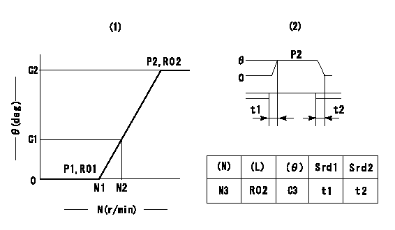
(1)Adjusting range
(2)Step response time
(N): Speed of the pump
(L): Load
(theta) Advance angle
(Srd1) Step response time 1
(Srd2) Step response time 2
1. Adjusting conditions for the variable timer
(1)Adjust the clearance between the pickup and the protrusion to L.
----------
L=1.5+-0.2mm N3=800r/min C3=(4deg) t1=2--sec. t2=2--sec.
----------
N1=1200++r/min N2=1400r/min P1=0kPa(0kgf/cm2) P2=392kPa(4kgf/cm2) C1=2.5--deg C2=4+-0.3deg R01=0/4load R02=4/4load
----------
L=1.5+-0.2mm N3=800r/min C3=(4deg) t1=2--sec. t2=2--sec.
----------
N1=1200++r/min N2=1400r/min P1=0kPa(0kgf/cm2) P2=392kPa(4kgf/cm2) C1=2.5--deg C2=4+-0.3deg R01=0/4load R02=4/4load
Speed control lever angle
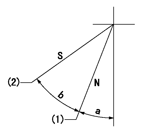
N:Pump normal
S:Stop the pump.
(1)Rack position = aa
(2)Rack position bb
----------
aa=16mm bb=1mm
----------
a=30deg+-5deg b=29deg+-5deg
----------
aa=16mm bb=1mm
----------
a=30deg+-5deg b=29deg+-5deg
0000000901

(1)Pump vertical direction
(2)Position of timer's threaded hole at No 1 cylinder's beginning of injection
(3)-
(4)-
----------
----------
a=(60deg)
----------
----------
a=(60deg)
Stop lever angle

(Rs) rack sensor specifications
(C/U) control unit part number
(V) Rack sensor output voltage
(R) Rack position (mm)
1. Confirming governor output characteristics (rack 15 mm, span 6 mm)
(1)When the output voltages of the rack sensor are V1 and V2, check that the rack positions R1 and R2 in the table above are satisfied.
----------
----------
----------
----------
Information:
The primary fuel filter should be cleaned, and the secondary (main) fuel filter element replaced, as follows: 1. When the fuel pressure gauge (if equipped) indicates low fuel pressure.2. When the engine has a noticable loss of power.3. Every 500 service hours of operation if the engine is not equipped with a fuel pressure gauge.
Fuel leaked or spilled onto hot surfaces or electrical components can cause a fire. Disconnect the battery (turn disconnect switch OFF) when changing fuel filters.
Do not fill fuel filters with fuel before installing them. Contaminated fuel will cause accelerated wear to fuel system parts.
Close the fuel supply valve at the tank before servicing filters. Open the valve after filter servicing is completed.Cleaning Primary Filter
Use all cleaning solutions with care.
1. Loosen the nut (1) on the filter cover and lower the filter case (3).2. Remove the element (2). Wash the cover and element in clean nonflammable solvent.3. Reinstall the element.4. Install the element and case onto the cover into the case.5. Tighten the bolt.Changing Secondary Filter
1. Unscrew filter element. Throw away the used element. 2. Make certain all of the used element seal is cleaned from the filter base. 3. Coat the seal of the new element with clean diesel fuel.4. Install the filter by hand. When the seal contacts the base, tighten 3/4 turn more.There are rotation marks 90° apart on the filter. Use these as a guide for proper tightening.5. Start the engine and check for leaks. If the engine will not start, prime the fuel system.