Information injection-pump assembly
ZEXEL
101691-9662
1016919662
Rating:
Cross reference number
ZEXEL
101691-9662
1016919662
Zexel num
Bosch num
Firm num
Name
Calibration Data:
Adjustment conditions
Test oil
1404 Test oil ISO4113 or {SAEJ967d}
1404 Test oil ISO4113 or {SAEJ967d}
Test oil temperature
degC
40
40
45
Nozzle and nozzle holder
105780-8140
Bosch type code
EF8511/9A
Nozzle
105780-0000
Bosch type code
DN12SD12T
Nozzle holder
105780-2080
Bosch type code
EF8511/9
Opening pressure
MPa
17.2
Opening pressure
kgf/cm2
175
Injection pipe
Outer diameter - inner diameter - length (mm) mm 6-2-600
Outer diameter - inner diameter - length (mm) mm 6-2-600
Overflow valve opening pressure
kPa
157
123
191
Overflow valve opening pressure
kgf/cm2
1.6
1.25
1.95
Tester oil delivery pressure
kPa
157
157
157
Tester oil delivery pressure
kgf/cm2
1.6
1.6
1.6
Direction of rotation (viewed from drive side)
Right R
Right R
Injection timing adjustment
Direction of rotation (viewed from drive side)
Right R
Right R
Injection order
1-4-2-6-
3-5
Pre-stroke
mm
3.4
3.35
3.45
Beginning of injection position
Drive side NO.1
Drive side NO.1
Difference between angles 1
Cal 1-4 deg. 60 59.5 60.5
Cal 1-4 deg. 60 59.5 60.5
Difference between angles 2
Cyl.1-2 deg. 120 119.5 120.5
Cyl.1-2 deg. 120 119.5 120.5
Difference between angles 3
Cal 1-6 deg. 180 179.5 180.5
Cal 1-6 deg. 180 179.5 180.5
Difference between angles 4
Cal 1-3 deg. 240 239.5 240.5
Cal 1-3 deg. 240 239.5 240.5
Difference between angles 5
Cal 1-5 deg. 300 299.5 300.5
Cal 1-5 deg. 300 299.5 300.5
Injection quantity adjustment
Adjusting point
-
Rack position
12.2
Pump speed
r/min
1500
1500
1500
Average injection quantity
mm3/st.
73.5
71.9
75.1
Max. variation between cylinders
%
0
-3.5
3.5
Basic
*
Fixing the rack
*
Standard for adjustment of the maximum variation between cylinders
*
Injection quantity adjustment_02
Adjusting point
-
Rack position
9.7+-0.5
Pump speed
r/min
300
300
300
Average injection quantity
mm3/st.
9.5
7.7
11.3
Max. variation between cylinders
%
0
-10
10
Fixing the rack
*
Standard for adjustment of the maximum variation between cylinders
*
Remarks
Adjust only variation between cylinders; adjust governor according to governor specifications.
Adjust only variation between cylinders; adjust governor according to governor specifications.
Injection quantity adjustment_03
Adjusting point
A
Rack position
R1(12.2)
Pump speed
r/min
1500
1500
1500
Average injection quantity
mm3/st.
73.5
72.5
74.5
Basic
*
Fixing the lever
*
Injection quantity adjustment_04
Adjusting point
B
Rack position
R1-0.7
Pump speed
r/min
800
800
800
Average injection quantity
mm3/st.
54.7
52.7
56.7
Fixing the lever
*
Injection quantity adjustment_05
Adjusting point
I
Rack position
15.7+-0.
5
Pump speed
r/min
150
150
150
Average injection quantity
mm3/st.
77.5
77.5
97.5
Fixing the lever
*
Rack limit
*
Timer adjustment
Pump speed
r/min
1250--
Advance angle
deg.
0
0
0
Remarks
Start
Start
Timer adjustment_02
Pump speed
r/min
1200
Advance angle
deg.
0.5
Timer adjustment_03
Pump speed
r/min
1500
Advance angle
deg.
1
0.5
1.5
Remarks
Finish
Finish
Test data Ex:
Governor adjustment
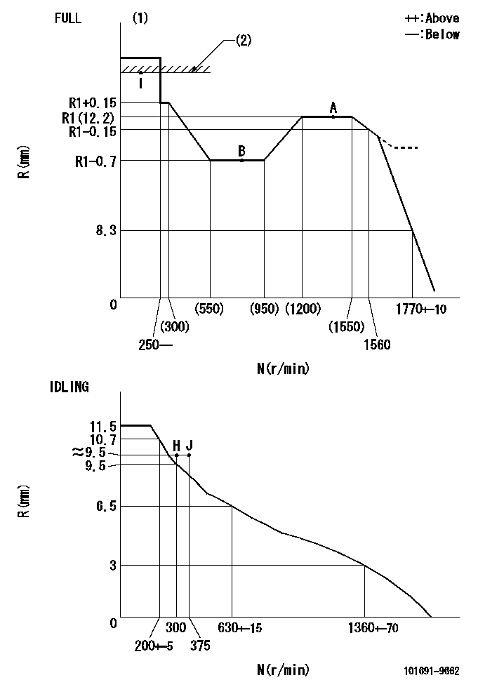
N:Pump speed
R:Rack position (mm)
(1)Torque cam stamping: T1
(2)RACK LIMIT
----------
T1=C06
----------
----------
T1=C06
----------
Speed control lever angle

F:Full speed
I:Idle
(1)Stopper bolt set position 'H'
----------
----------
a=26.5deg+-5deg b=41deg+-3deg
----------
----------
a=26.5deg+-5deg b=41deg+-3deg
Stop lever angle

N:Pump normal
S:Stop the pump.
----------
----------
a=37deg+-5deg b=40deg+-5deg
----------
----------
a=37deg+-5deg b=40deg+-5deg
Timing setting

(1)Pump vertical direction
(2)Position of timer's threaded hole at No 1 cylinder's beginning of injection
(3)-
(4)-
----------
----------
a=(60deg)
----------
----------
a=(60deg)
Information:
Oils
Hot oil and components can cause personal injury. Do not allow hot oil or components to contact the skin.Keep all exhaust manifold and turbocharger shields in place to protect hot exhaust from oil spray in the event of a line, tube or seal failure.Always wear protective glasses when working with batteries. Battery electrolyte contains acid and can cause injury. Avoid contact with the skin and eyes. Wash hands after touching batteries and connectors. Use of gloves is recommended.Fire or Explosion Prevention
A flash fire can result in personal injury if crankcase covers are removed within fifteen minutes after an emergency shutdown.Fire may result from lubricating oil or fuel sprayed on hot surfaces causing personal injury and property damage. Inspect all lines and tubes for wear or deterioration. They must be routed, supported or clamped securely. Tighten all connections to the recommended torque.Exhaust shields (if equipped), which protect hot exhaust components from oil or fuel spray in the event of a line, tube or seal failure, must be installed correctly.Determine whether the engine will be operated in an environment in which combustible gases could be drawn through the air inlet system. These gases could cause the engine to overspeed, which in turn could seriously damage the engine and result in bodily injury or property damage. If your application involves the presence of combustible gases, consult your Caterpillar dealer to obtain additional information concerning protection devices suitable for the application involved.All fuels, most lubricants and some coolant mixtures are flammable. Diesel fuel is flammable. Gasoline is flammable. The mixture of diesel and gasoline fumes are extremely explosive. Keep all fuels and lubricants stored in properly marked containers and away from all unauthorized persons.Provide adequate and safe disposal of waste oil and petroleum products. Follow all federal, state and local laws and regulations regarding waste oil and hazardous waste.Oil and fuel filters must be properly installed and tightened when being changed.Remove all flammable materials such as fuel, oil and other debris before they accumulate on the engine.Collect drained liquids and wipe up all oil, fuel or coolant spills. Remember; all fuels, most lubricants and some coolant mixtures are flammable as well as creating a hazard to walking if spilled.DO NOT SMOKE while refueling or in a refueling area. DO NOT SMOKE in areas where batteries are charged, or where flammable materials are stored. Store all oily rags or other flammable material in a protective container, in a safe place.Do not weld or flame cut on pipes or tubes that contain flammable fluids. Clean them thoroughly with nonflammable solvent before welding or flame cutting on them.Clean and tighten all electrical connections. Check regularly for loose or frayed electrical wires. Refer to maintenance schedules for interval. Have all loose or frayed electrical wires tightened, repaired or replaced before operating the engine.Wiring must be kept in good condition, properly routed and firmly attached. Routinely inspect wiring for wear or deterioration. Loose, unattached, or unnecessary wiring must be eliminated. All wires and cables must be of